©2005 VIDERE DESIGN STH-DCSG USER’S MANUAL STH-DCSG/-C Stereo Head User’s Manual April, 2005 ©2005 Videre Design 1
©2005 VIDERE DESIGN STH-DCSG USER’S MANUAL 7.3 7.4 7.5 7.6 Table of Contents Video Digitization Parameters .................................................... 19 Subsampling................................................................................ 20 Frame Rates ................................................................................ 20 Firmware Parameters .................................................................. 20 Introduction ..................................................
©2005 VIDERE DESIGN STH-DCSG USER’S MANUAL Figures and Tables Figure 1-1 Sequence taken by the MT9V022.............................................. 5 Figure 2-1 SVS main program window....................................................... 6 Figure 3-1. Physical layout of the STH-DCSG/-C stereo head. .................. 8 Figure 3-2 Schematic of the STH-DCSG/-C electronics............................. 9 Figure 4-1 Host PC low-level software structure. .....................................
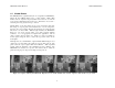
©2005 VIDERE DESIGN STH-DCSG USER’S MANUAL 1.1 1 Introduction Characteristics • Micron MT9V022 CMOS imagers Global shutter Simultaneous exposure and readout 640x480 maximum image size 1/3” format High sensitivity, low noise Low pixel cross-talk The STH-DCSG is a compact, low-power digital stereo head with an IEEE 1394 digital interface. It consists of two 640x480 (VGA), progressive scan CMOS imagers mounted in a rigid body, and a 1394 peripheral interface module, joined in an integral unit.
©2005 VIDERE DESIGN STH-DCSG USER’S MANUAL 1.2 Global Shutter The STH-DCSG has a global shutter (the “G” designation in STH-DCSG). Almost all other CMOS imagers have a rolling shutter. With rolling shutter, each row of pixels is exposed just before it is read out. So each row is exposed at a different time from other rows. This leads to motion blur – a skewing of moving objects from top to bottom. Global shutter, on the other hand, exposes every pixel at the same time.
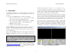
©2005 VIDERE DESIGN STH-DCSG USER’S MANUAL Start the SVS main program, smallv(.exe) or smallvcal(.exe), on the host computer. You should see a screen as in Figure 2-1. The message window should indicate that the “DCS Digital Stereo Interface” is present. If not, go back to software installation (Section 4.2), and follow the instructions for configuring the correct capture library. 2 Quick Start The STH-DCSG/-C normally comes assembled with the lenses mounted.
©2005 VIDERE DESIGN STH-DCSG USER’S MANUAL (Section 7.3). Images can be saved using the File menu. A more complete description of the video capture program is in Section 7. The SVS programs are described in the SVS User’s Manual, and the SVS Calibration Addendum, documentation that comes with that software. It is helpful to review Section 7 in conjunction with the SVS documentation.
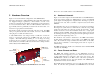
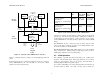
©2005 VIDERE DESIGN STH-DCSG USER’S MANUAL There are no user-settable switches on the STH-DCSG/-C. 3 Hardware Overview 3.1 Figure 3-1 shows the hardware configuration of the STH-DCSG/-C. Figure 3-2 shows the design of the internal hardware of the STH-DCSG/-C. In the stereo imager module, two CMOS imagers, each of size 640x480 pixels, digitize incoming light into a digital stream. The imagers operate in progressive mode only, that is, each line is output in succession from the full frame.
©2005 VIDERE DESIGN STH-DCSG USER’S MANUAL Left Imager Imager module 8-bit pixels 12 MHz per imager Frame size Frame rate, 60 Hz (default) Frame rate, 50 Hz option Format 0, Mode 3 YUV 16 bits Left image on Y, right image on UV 640x480 3.75, 7.5, 15, 30 Hz 3.125, 6.25, 12.5 25 Hz Format 0, Mode 1 YUV 16 bits Left image on Y, right image on UV 320x240 7.5, 15, 30, 60 Hz 6.25, 12.
©2005 VIDERE DESIGN STH-DCSG USER’S MANUAL electrical line frequency is 50 Hz. For these countries, there is a mode to change the frame rates of the STH-DCSG to sub-multiples of 50 Hz. These frame rates are shown in the last column of Table 1. from just counting the number of bytes in each frame, because there are blank cycles on the bus, when no data is being transmitted, even though the bandwidth is reserved.
©2005 VIDERE DESIGN STH-DCSG USER’S MANUAL through installation steps for the low-level drivers. You may need your MS Windows OS CD to install some files. 4 Installing the 1394 Host Card and Capture Software The STH-DCSG must be powered from the IEEE 1394 bus. Desktop PCs supply power to the bus; laptops do not. See Section 5 for information about cabling and power for the IEEE 1394 bus. The STH-DCSG/-C connects to a host computer via a digital 1394 interface.
©2005 VIDERE DESIGN STH-DCSG USER’S MANUAL In MSW Windows, execute the file bin\setup_dcs.bat. This will copy svsdcs.dll/lib as the interface libraries. only way to run the SVS calibration procedures is through the smallvcal(.exe) application. Under Linux, copy the following file in the bin/ directory: smallv(.exe) is a GUI-based application that allows the user to exercise the capture and stereo functions of the STH-DCSG/-C. It is described in earlier sections of this document. dcscap.
©2005 VIDERE DESIGN STH-DCSG USER’S MANUAL capability of supplying power, and come with an adapter for supplying power to the 1394 cable through a wall transformer. 5 IEEE 1394 Interface Any 1394 card is suitable, as long as it conforms to OHCI (open host controller interface) specifications. All current cards do, but some older cards may not. Digital image information is transferred from the STH-DCSG/-C to the host PC via a 1394 cable.
©2005 VIDERE DESIGN STH-DCSG USER’S MANUAL Figure 5-1 shows the two configurations for supplying power. A wall transformer converts line voltage to 12 VDC, and is plugged into a hub or the PC Card. PC Card with power port IEEE 1394 hub with power port IEEE 1394 Cable IEEE 1394 Cable IEEE 1394 Cable to PC Power – 12 VDC, >150 A Power – 12 VDC, >150 A Figure 5-1 External power supply connections. On the left is power supplied to a PC Card with a power port.
©2005 VIDERE DESIGN STH-DCSG USER’S MANUAL Once the threads are engaged, continue screwing it on until it seats firmly. You can snug it down, but do not tighten it excessively, since this can damage the lens and the lens holder threads. 6 Lenses Removing the lens is the reverse process: unscrew the lens counterclockwise. There will be some initial resistance, and then it should unscrew smoothly. The STH-DCSG/-C uses standard C or CS-mount lenses.
©2005 VIDERE DESIGN STH-DCSG USER’S MANUAL 6.8 Range Resolution Range resolution is the minimum distance the stereo system can distinguish. Since stereo is a triangulation operation, the range resolution gets worse with increasing distance from the stereo head. The relationship is: r2 ∆r = ∆d , bf where b is the baseline between the imagers, f is the focal length of the lens, and ∆d is the smallest disparity the stereo system can detect. For the STHDCSG/-C, b is 90 mm, and ∆d is 0.
©2005 VIDERE DESIGN STH-DCSG USER’S MANUAL Lens focal length Horizontal FOV Vertical FOV 2.8 mm 69 deg 54 deg 4.0 51 40 8.0 27 20 16 14 10 Table 3 Horizontal and vertical field of view for different lens focal lengths.
©2005 VIDERE DESIGN STH-DCSG USER’S MANUAL two monochrome and one or two RGB color channels. The primary color channel corresponds to the left image, which is the reference image for stereo. The right image color channel is also available. The color images can be de-warped, just like the monochrome images, to take into account lens distortion (see the Small Vision System User’s Manual). 7 User Controls The CMOS imagers are fully controllable via the 1394 interface.
©2005 VIDERE DESIGN STH-DCSG USER’S MANUAL The STH-DCSG has on-chip gamma correction that can be turned on or off. When on, it compresses the 10-bit output of each pixel into 8 bits. The compression occurs mostly in the higher light levels. With on-chip gamma correction, the STH-DCSG can handle larger dynamic ranges of light, such as occur outdoors with bright sunlight and deep shadow. will increase the depth of field and give better optical performance. Indoors, the iris usually is fully open.
©2005 VIDERE DESIGN STH-DCSG USER’S MANUAL the light on the image will be adjusted by changing the exposure. binning will take place on the imager, which then transmits a 320x240 imager. Using SetSample(1,2) means that binning will take place on the host. In this case, the imager transmits all 320x240 pixels, so the maximum frame rate is lower. This is the greyed-out line in the table.
©2005 VIDERE DESIGN STH-DCSG USER’S MANUAL fixed in the firmware. The one changeable parameter is for 50 Hz or 60 Hz operation (Section 3.3). use 50 Hz operation, check the box, and then press the Save button. This choice is downloaded and stored in the device, and will cause 50 Hz operation every time the STH-DCSG is accessed. To change back to 60 Hz, uncheck the box and again save it to the device.
©2005 VIDERE DESIGN STH-DCSG USER’S MANUAL 8 Interface Software API Please see the Small Vision System manual for information about the software API for capturing and saving images.
©2005 VIDERE DESIGN STH-DCSG USER’S MANUAL 9 Physical Diagram Dimensions and The larger hole is threaded for a ¼-20 machine screw (standard tripod mounting screw). The two smaller holes are threaded for 6-32 machine screws. Mounting The diagram below shows the physical dimensions for the STH-DCSG/-C.
©2005 VIDERE DESIGN STH-DCSG USER’S MANUAL Size 1.725” high x 5.2” long x 1.3” deep (excluding lenses) Weight 190 g (6.7 oz), without lenses 71 g (2.5 oz) for 4.0 mm lenses Stereo Baseline 9 cm SVS software Linux kernel 2.4, 2.6 MSW 98SE, ME, 2000 and XP Environmental 0-40 C, < 90% humidity (noncondensing) 10 Technical Specifications 10.1 Specifications Imagers 1/3” format CMOS (Micron MT9V022) 640x480 active area Progressive scan Color or monochrome Digital Camera Specification Version 1.
©2005 VIDERE DESIGN STH-DCSG USER’S MANUAL 10.2 Imager Response - Color 10.
©2005 VIDERE DESIGN STH-DCSG USER’S MANUAL 10.
©2005 VIDERE DESIGN STH-DCSG USER’S MANUAL 11 Technical Support For technical support, please contact Videre Design by email or FAX. Videre Design 865 College Avenue Menlo Park, CA 94025 Fax: (650)323-3646 Email: support@videredesign.com Technical information about stereo algorithms and stereo calibration can be found at www.ai.sri.com/~konolige/svs.