VX2200 DIGITAL SYSTEM TECHNICAL MANUAL EDITION 1.
PAGE 2 of 68 VX2200 TECHNICAL MANUAL VER1.
CONTENTS PAGE Manual introduction System introduction Digital door panels Digital door panel programming flow chart 4000 Series / 8000 Series Functional door panels Vandal resistant functional door panels (Amplifier 138) Camera’s Video Distribution Control equipment Power supplies Digital time clock Video switching PCB Isolation card Bus exchange device Concierge unit Concierge unit programming flow chart 2280 Bus interface device Audio telephones Audio apartment station Art.
MANUAL INTRODUCTION The information in this manual is intended as an installation and commissioning guide for the VX2200 Digital system. This manual should be read carefully before the installation commences. Any damage caused to the equipment due to faulty installations where the information in this manual has not been followed is not the responsibility of Videx Security Ltd. VIDEX run free training courses for engineers who are not familiar with the Videx product range.
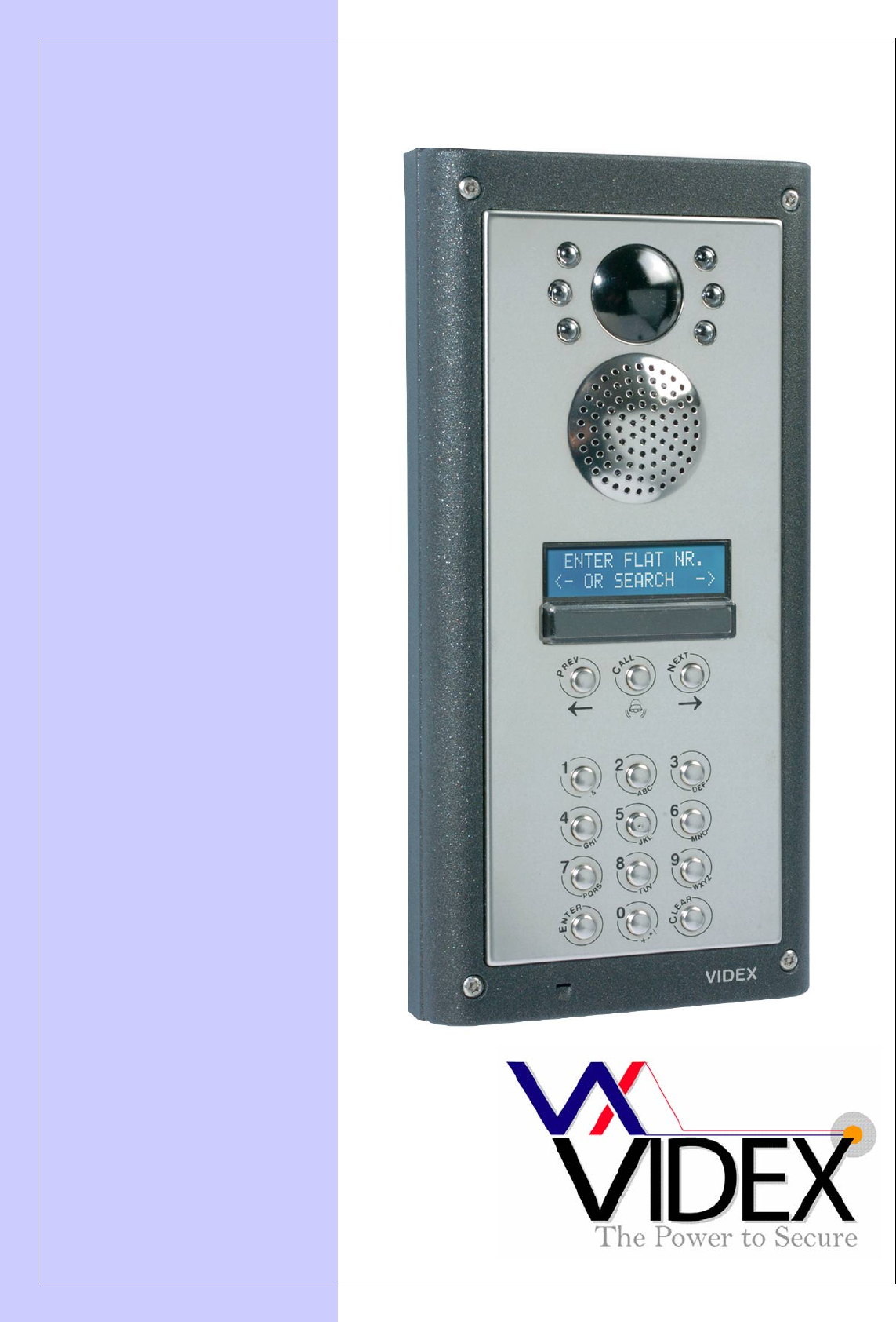
DIGITAL PANELS Digital panels are available in the 8000 Series, 4000 Series and vandal resistant. The difference is mainly aesthetics; they all share the same connections, volume adjustments and programming menu. Digital panels can also be programmed with a PC using the SP37 programming kit. The PC connects to the panel via a jack socket located in the rear of the panel. Call progress is shown on a 2 line back lit LCD display.
VOLUME ADJUSTMENT There are four volume adjusters on the door panel as follows:- Speaker volume Microphone volume Balance between mic volume and speaker volume Voice annunciation volume (May also be labelled ‘V.PB CHIP’ MAKING A CALL All stages of the call will be acknowledged via the LCD display, voice annunciation and call progress tones. Additionally, the panel will also prompt the user with information on how to progress to the next stage of the call.
DIGITAL PANEL PROGRAMMING LCD DISPLAY ENTER PRESET FACTORY CODE 0+6x1 (0111111) EXAMPLE CODE : ****** CODE : ****** CODE : ****** NEW : **** CODE : ****** NEW : **** TRADE C : xxxxxx NEW : xxxx TRADE C : NEW : 1234 MEM.LOCATION: xxx MEM.LOCATION: 15 FLAT : NEW : xxxxxx FLAT : NEW : 15 ID PHONE : NEW : xxx ID PHONE : NEW : 15 2206N N. : 0 NEW : xx 2206N N.
CONTINUED FROM PREVIOUS PAGE SELECT 0 - 5 SET SPEECH PLAYBACK (0 to 2) 0=NO 1=ST 2=CMB SPEECH BOARD 0=NO 1=ST 2=CMB SPEECH BOARD MASTER/SLAVE SETTING (0 = SLAVE, 1=MASTER) MASTER : NOT 1 = YES MASTER : YES 0 = NOT AUTOMATIC FLAT TEST (1 or ENTER) 1 = TEST FLAT “ENTER” = END TEST FLAT 101 ID PG 1-1 SELECT 0 - 2 (*) NOTE 2-3 SELECT 0 or 1 OK SELECT 1 or ENTER (*) NOTE 2-3 SYSTEM READY TO USE ENTER FLAT NR.
DIGITAL PANEL MODE The digital panel can be set to either MAIN MODE or LOCAL MODE. MAIN mode should only be used for panels that call all users and on systems that include 2206N devices (One per block or one for every 180 apartments), use LOCAL mode for all other applications. To set a digital panel as MAIN MODE, power up with the 0 button pressed. To set as LOCAL MODE, power up with ENTER pressed (The mode can also be changed via the PC programming software.
4000 SERIES/8000 SERIES FUNCTIONAL PANELS 4203 4283 8203 The 4000 and 8000 Series functional panels are of modular design each being capable of expansion up to 64 call buttons (only 32 buttons on the 4283 combined camera and speaker module). Programming options are carried out via dip-switches. Call progress tones are used to indicate the status of a call.
VOLUME ADJUSTMENT There are three volume adjusters on the door panel as follows:Speaker volume Microphone volume Balance between microphone volume and speaker volume CONNECTING ADDITIONAL BUTTONS Up to 64 buttons (32 on the 4283) can be connected to the modules using an X-Y matrix as shown here. When using the 4000 Series button modules you will notice a number of jumpers on these modules which allow you to select if the buttons are common or isolated from each other.
DIP SWITCHES (4283) All DIP-SWITCH CHANGES MUST BE CONFIRMED BY POWERING DOWN THE MODULE AND THEN POWERING UP AGAIN. Nr.1 OFF ON Setting Up = Slave = Master (default) Nr.2 OFF ON OFF ON OFF ON OFF Nr.3 OFF OFF ON ON OFF OFF ON Nr.4 OFF OFF OFF OFF ON ON ON ON ON ON Nr.5 OFF ON Setting Up = 1 min = 2 min Nr.6 OFF ON Setting Up = 2 seconds = 6 seconds Nr.7 OFF ON OFF ON OFF ON OFF ON Nr.8 OFF OFF ON ON OFF OFF ON ON Nr.9 OFF OFF OFF OFF ON ON ON ON Switch 1 sets the panel as a Master or Slave.
VANDAL RESISTANT FUNCTIONAL PANELS This module is used in the VX2200 2 wire audio, 6 wire video functional vandal resistant door panels and includes all features required for audio & video installations. A 13.8Vdc PSU is required to power this system. Up to 23 buttons can be connected to this module. (This module cannot be used with 316x phones).
1. 2. 3. 4. Power down the 138 amplifier Connect the plug (5 or 6) to A,B,C or D depending on the setting to program as outlined below. Power up the 138 amplifier Listen to the beeps from the 138 amplifier, When the correct number is reached as outlined below, remove the link between the plug and A,B,C or D. 5. A long confirmation beep will confirm the new setting has been stored.
CAMERA MODULES All camera modules are available in mono or colour. The mono cameras include infra-red illumination to illuminate a subject in poor lighting conditions (max range 80cm). The colour cameras include white LED’s which switch on during a call. With the exception of the 830 and 830NC, the cameras are all able to support both balanced and composite video outputs which is selectable, adjusting the position of the jumpers.
VIDEO DISTRIBUTION COAX VIDEO The version to the left is the Art.894 and the version to the right is the 894I. Both versions are 4 way video splitters therefore one is required for every four videophones. The 894I also benefits from over current protection for each of the four 20V (500mA max) outputs meaning, if a short appears on those connections or a fault towards the monitor occurs then the 20V to that output will be disconnected to allow all other outputs to continue working.
CONTROL EQUIPEMENT As there are many variations of control cabinet available (Audio, video, with isolation, multiple door etc). The components that make up a control cabinet are listed below:- 13.8Vdc SYSTEM PSU Battery backup is a standard feature of these PSU’s. We recommend a 7Ah sealed lead acid battery. 1A, 2A, 3A & 4A PSU’s are normally used on this system, all of which have a regulated output voltage of 13.8Vdc. DC out and battery trickle charge are independently fused.
TIME CLOCK The 701T is a BST/GMT time clock with 6 programmable on/off periods and two modes of operation. The first mode being a standard time clock mode whereby the dry contact relay output triggers for the length of an on/off period. The second mode is known as the trade button mode and only operates the relay when the trade input is triggered and during an active on/off period. The relay would then stay energised for a programmed time (01-99 seconds).
TIME CLOCK PROGRAMMING Programming is carried out by means of the four push buttons. The mode button advances through the modes beginning with mode 1 which allows the editing of the time and date, mode 2 – 7 allows the editing of the time bands and mode 8 allows the editing of the relay time in trade mode (Note: mode 8 only appears in trade mode).
VX123 VIDEO SWITCHING PCB The VX123 is used on multiple door video systems to switch the video from a single door to the bus. Each PCB can control up to four video panels. Multiple PCB’s can be used to expand the system. A green LED indicates when a panel is connected to the bus.
OPERATION In stand-by the phones connected to the 2204N are physically disconnected from the main BUS. During a call the selected channel will be connected to the main bus, the green LED next to the channel will illuminate for the length of the call. PROGRAMMING (DIP-SWITCHES) The dip-switches are used to address the PCB. The address of the PCB must correspond with the address of the telephone in the apartment.
BUS EXCHANGE DEVICES (2206N) The 2206N is a powerful device which allows the system to be expanded up to 998 apartments. There are two applications in which this unit can be used. The first application is a system with both main entrances and sub entrances/blocks (Main entrances call all apartments on a system and sub/block entrances only call the apartments in their own block). In this application, one 2206N would be required for each block.
JUMPERS Jumpers JP2 and JP3 are used to set the video signal type to either balanced (Twisted pair) or coax (Composite video) Jumpers JP4 and JP5 are used to terminate the video end of line. They should only be in the end of line position on the last 2206N DIP-SWITCHES Dip-switches 1 – 4 are used to address the 2206N. Each 2206N must have a unique address. The address will be used when programming the main entrance panels on a system.
CONCIERGE UNIT (2210A, 2210V) The Digital Concierge has an alphanumerical keypad (“0” to “9”, “*”, “#”, and “A” up “H” by means of four buttons with double letter function), a mode button (night, day, off) and a 2 line 16 character “” and a door open button LCD display with back light. This device enables the intercommunication between concierge and user, door and concierge, door and user and two users, the booking of up to 48 user calls and the storing of up to 48 user activated alarms.
3. The operator can delete the call by pressing “#” or call them back by pressing “*”: a) If the operator chooses to delete the call, the concierge restarts from step (2) showing the next booked call (if there are other booked calls), otherwise it goes back to the stand-by condition (the display shows the message relevant to selected operation mode); b) If the operator choose to take the call, the concierge calls the user; 4.
TRIMMERS Two POT’s are also located within the concierge. The one to the right of the PCB adjusts the speech balance towards the apartments and the one to the left adjusts the speech balance towards the doors. PROGRAMMING The concierge has two main operational modes (Main and standard).Main mode is only used on systems which include 2206N devices. Standard mode is used for all other system types.
2280 BUS INTERFACE The Art.2280 enables the connection of either the Videx Telephone Interface (Art.380) or the Videx apartment station (Art.500MM) to the VX2200 system. Using this device it is possible to carry out all the functions available on the VX2200. For example, answer a call from the door panel (and if necessary open the door), call the concierge (if present on the system) and intercommunicate with another user (via concierge). The system draws power directly from the “2 wire” Bus (Less than 0.
Audio Telephones (3171, 3172 & 3176) The Art.3171 is a digital intercom based on the “2 Wire BUS”, it includes a door-open button and a service button plus an electronic call tone with a 3 level volume control which can be adjusted by the user. Internally, the intercom has an 8 way dip-switch to set the PHONE ID, terminals for connecting to the bus and other functions and a trimmer (VR1) to adjust the microphone volume. It is possible to connect up to 180 intercoms on the same bus.
OPERATION To answer a call and open the door: Pick the handset up and speak with the visitor (or concierge); press the ‘ ’ button (if it is an external call) to open the door (an acoustic signal will be emitted and the door will be opened for the time programmed) or replace the handset to end the conversation; if the call is local (local bell), the call tone will have a different tone.
AUDIO APARTMENT STATION (5178) The 5178 is an audio apartment station available in white, silver or carbon fibre ABS plastic and is a surface mount unit which connects to the VX2200 bus via a 4 wire bus. The apartment station has half duplex speech (Hands free speech) and the facility to switch into simplex speech mode by holding the talk/answer button down during a call. The apartment station includes the following buttons.
PROGRAMMING NUMBER OF RINGS (FACTORY SET 6 RINGS) Press and hold “ ” (for approx 10 seconds) until the unit emits a beep. Press “ ” as many times as the number of rings required (i.e. 6 presses = 6 rings with a maximum of 9 rings) Once the number of rings required has been reached, wait 3 seconds for the exit beep. The new value is now stored. PROGRAMMING THE PRIVACY DURATION (FACTORY SET WITH OUT TIMEOUT) Press and hold “ ” (for approx 10 seconds) until the unit emits a beep.
VIDEOPHONES 3371(Mono) 3471(Colour) 3376(Mono) 3476(Colour) 3980 (Back plate) The Art.3371 (3471 colour) is a digital videophone based on a “6 Wire BUS”, it includes 5 push buttons as shown in the table below and the images above. The call is an electronic tone with a 3 level volume control which can be adjusted by the user. To connect the videophone to the “BUS”, use the PCB connector provided with the mounting plate Art.3980.
CONNECTIONS 1 2 3 4 5 6 7 8 9 10 11 12 13 14 15 16 17 18 Art.3371 – Description of the signals on the Art.
PROGRAMMING The programming of this videophone consists of the following stages: - Set the PHONE ID on the 8 way dip-switch shown on decimal/binary conversion table in this manual; - Set the video format, coax or balanced (non-coax).
Video monitor (5478, 5476) An intelligent Hands-free (surface or flush mounting) video monitor employing a colour 3.5” active matrix LCD display. The 5478 is available in white, silver and carbon fibre finishes and can be fitted with the optional flush kit or handset kit. The 5478 includes push buttons for “door open/concierge call”, “answer/camera recall”, “privacy on/off”, “Latching relay activation” and 2 service buttons plus 4 LED’s associated with the 4 main buttons.
19 LD 20 GND Auxiliary LED +12V input (LED next to door open button) Ground PROGRAMMING Setup is carried out using the push buttons on the front of the unit and the dip-switches located on the rear of the unit. An eight way dip-switch bank is used to set the address of the apartment as shown in the decimal/binary conversion chart in this manual. Additionally there is a 4 bank dip switch which is used to select the video type (either coaxial or balanced video twisted pair).
Video monitor (SL5478) The SL5478 is a slimline version of the 5478. This model is surface mount only and unlike the 5478 does not require a separate mounting plate. Connections, programming, and functions are the same as the 5478 with the exception of the “●●” button which is non-latching on the SL5478. The “ “ button is also used instead of the “●●” button when programming the call tone melody. The 4 way dip switch is also different to the 5478 as shown below.
Description NOT USED +12V output to power 894 video splitter +15-20dc input to power video monitor Balanced video signal 1 Balanced video signal 2 or coax centre core Video ground +12V output (Max 100mA) NOT USED NOT USED +12V input Bus 0V Bus line Local door bell input (Active low) Alarm input (Active low) Service button output (Open collector) Triggered by holding Door monitoring LED input (+12Vdc to trigger) for more than 3 seconds Signal T +VD +20 V1 V2 +Vo 2 4 +VI L1 LB AL5 SB DL PROGRAMMING Address
Press (several times or hold pressed) “ ” to increase the speech volume or the “ ” button to decrease the volume. Once the required volume level is reached, wait approx 3 seconds or press again the “ ” button. The “privacy” LED switches OFF while the “talk” LED switches back ON. VR5478 PROGRAMMING MENU’S The video monitor has two menus for programming and adjustment functions: 1.
Video monitor (3678) The 3678 is a wall mount colour videophone with 3.5” TFT OSD monitor. Both handset and handsfree (Half duplex) speech are available along with the facility to switch into simplex speech mode by holding the talk/answer button down for more than 3 seconds. Additional features include timed privacy, an auxillary outout and LED’s to indicate call answer, privacy active and door release. An Art.5980 mounting plate is required for this monitor.
3678 PROGRAMMING MENU The video monitor has two menus for programming and adjustment functions: 1. The 1st menu can be entered when the system is in stand-by and allows the following settings: Privacy duration, melody volume, melody, number of rings. (Note: 20Vdc must be on for this function) 2.
EXTENSION SOUNDER (512D) EXTENSION RELAY (512DR) 512DR 512D Compatible with the “2 wire” BUS and has an 8 way Dip-switch to program the address of the device. Up to 3 units can be addressed with the same number (Ex.: 1 intercom and 2 extension sounders to be operated with the same apartment number). The call tone is different according to the origin of the call (Main entrance call or local door bell).
INSTALLATION DIRECTIONS Installation and maintenance must be carried out by specialized engineers only. Do not install the components of the system in humid environments or near heat sources. Make sure that the power supplies present in the system are not connected to the mains during the installation of devices. Before powering the system, check that the cabling is correct.
CABLE GUIDE The following table outlines the maximum resistance allowed from furthest point to furthest point. Cable sizes Distance up to 100m 200m 350m 500m (-) (L) (V1)* (V2)* Signals 0.3mmsq AWG22 0.6mmsq AWG19 1.0mmsq AWG17 1.5mmsq AWG15 (-)* (+20)* Signals 0.6mmsq AWG19 1.0mmsq AWG17 1.5mmsq AWG15 Max. Resistence 7.5 Ohms Max. Resistence 5 Ohms Supply cables ( power supply outdoor station): they must have a minimum size of 1.
CAT5 NOTES: Only recommended for systems with up to 20 apartments and maximum distances of 70m for mono video or 100m for colour video. Calculations based on a DC loop resistance <0.188 Ohm/m (Converts to 94 Ohm/km). The following cores should be used on video systems.
SPEECH ADJUSTMENT It is necessary to adjust the speech volume to have the best performance without “Larsen” effect (Feedback). It is advisable to carry out the following procedure: 1. Be sure that microphone volume and speaker volume trimmers are in the middle position ( access holes to the trimmers at the back of the panels); 2.
Dip-sw 2 =off Dip-sw 3 =off Dip-sw 2 =on Dip-sw 3 =off DIP-SWITCH setting DIP-SWITCH setting Dec. Nr. Art.
Dip-sw 2 =off Dip-sw 3 =on Dip-sw 2 =off Dip-sw 3 =on DIP-SWITCH setting DIP-SWITCH setting Dec. Nr. Art.
TROUBLE SHOOTING GUIDE PROBLEM FOUND The system has power but the front panel does not turn on. POSSIBLE CAUSE 1. 2. Front panel display shows “ERROR” and the unit makes acoustic intermittent signals at intervals of approx. 2 seconds. The system, at the moment of the call, is not able to let the extension ring, the front panel makes acoustic signals of line engaged and the display shows “Error”. The outdoor station makes the call correctly, but when the user answers, the communication is cut off.
PAGE 50 of 68 VX2200 TECHNICAL MANUAL VER1.
PAGE 51 of 68 VX2200 TECHNICAL MANUAL VER1.
PAGE 52 of 68 VX2200 TECHNICAL MANUAL VER1.
PAGE 53 of 68 VX2200 TECHNICAL MANUAL VER1.
PAGE 54 of 68 VX2200 TECHNICAL MANUAL VER1.
PAGE 55 of 68 VX2200 TECHNICAL MANUAL VER1.
PAGE 56 of 68 VX2200 TECHNICAL MANUAL VER1.
PAGE 57 of 68 VX2200 TECHNICAL MANUAL VER1.
PAGE 58 of 68 VX2200 TECHNICAL MANUAL VER1.
PAGE 59 of 68 VX2200 TECHNICAL MANUAL VER1.
PAGE 60 of 68 VX2200 TECHNICAL MANUAL VER1.
PAGE 61 of 68 VX2200 TECHNICAL MANUAL VER1.
PAGE 62 of 68 VX2200 TECHNICAL MANUAL VER1.
SYSTEM COMPONENTS 800 Series Digital Front Panels (2202M, 2202MR) These units are built into a double 800 series module (stainless steel/S or aluminium/A) and have a 2 line16 character LCD display, speaker unit and numeric keypad with either 8 alpha buttons [A-H] (VX2202/2202M) or 3 scroll buttons (VX2202R/2202MR) to navigate the “Repertory Names”. A PC based programming kit is also available (SP37) which includes software and serial cable to simplify the programming of large installations.
This unit isolates the telephones from the main bus preventing a single telephone from compromising the system. One PCB is required for every four handsets. (The L, -, +12, S1 & D terminals are isolated by this PCB). A piggy back video isolation PCB is also available for this audio isolation PCB (Available in both coax and non-coax video versions). Non-Coax Video Distributor & 20Vdc Video PSU isolation (316I) Video splitter PCB for no-coax video systems, One required for every four videophones.
Extension sounder (512D) Extension Sounder in a white plastic wall mount box. Connects directly to the 2 wire bus. Extension relay (512DR) As the 512D but with a dry contact relay (24V 100mA) instead of the sounder. Non-coax camera module (830/NC, 830C/NC) 800 series camera module with infrared illumination. “No coax” required. (Colour camera 830C/NC has white LED’s as oppose to IR LED’s) Coax camera (830, 830C) As above but for coax video systems. Use 830NC /830NC/C for non-coax camera.
SEDE LEGALE: Via G. Ceresani 1 – 60044 Fabriano (AN) Tel. 0732-626511 / fax 0732-626939 www.eqi.it SEDE DI JESI: Via G. Di Vittorio 4 ZIPA 2 – 60035 Jesi (AN) Tel. 0731-202064 / fax 0731-226376 customer@eqi.it Sistema qualità conforme alla norma ISO/IEC 17025 ISO/IEC 17025 compliant quality system Rapporto di Prova Compatibilità Elettromagnetica n°: RP LCE031910/01 E.M.C.
PAGE 67 of 68 VX2200 TECHNICAL MANUAL VER1.
Northern Office Videx Security Ltd Unit 4-7 Chillingham Ind. Est. Newcastle Upon Tyne NE6 2XX TEL 0870 300 1240 FAX 0191 224 5678 Southern Office 1 Osprey Trinity Park Trinity Way London E4 8TD FAX 0208 523 5825 TECHNICAL SUPPORT tech@videx-security.com TEL 0191 224 3174 FAX 0191 224 4938 http://www.videx-security.com PAGE 68 of 68 VX2200 TECHNICAL MANUAL VER1.