Voice Server Espero for ISDN II & PRI Manual 1.
Manual Voice Server Espero © Vidicode 2009
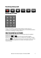
RecorderRecorder-keys desktop model Record Backward Stop Pause/Play Forward Skip Recorder keys 19” model On the 19” model the numerical keys and the recorder keys are combined. This is possible because depending on the selected procedure the function of the keys is always obvious. About the recorder keys on all models During recording and playback the recorder keys have the standard recorder key functions.
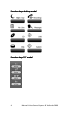
FunctionFunction-keys desktop model Function keys 19” model 4 Manual Voice Server Espero © Vidicode 2009
AlfaAlfa-numerical functions Manual Voice Server Espero © Vidicode 2009 5
Care and Maintenance Keep the Voice Server dry. If it gets wet, wipe it dry immediately with a soft, clean cloth. Liquids might contain minerals that corrode the electronic circuits. Use and store the Voice Server only in temperature conditions between 0 and 40 degrees Celsius. Temperature extremes can shorten the life of electronic devices and distort or melt plastic parts. Keep the Voice Server away from excessive dust and dirt.
Contents 1 Introduction ............................................................13 1.1 1.2 1.2.1 1.2.2 1.2.3 1.2.4 1.2.5 1.3 1.4 1.5 1.6 2 2.2.1 2.2.2 2.3 2.3.1 2.3.2 2.4 2.5 Network................................................................. 15 Search voice mail................................................... 16 Pass through connection system........................... 16 Audio compression for recording......................... 16 What is in the box? ...................................
4.2 4.3 4.4 4.5 4.6 4.7 4.8 4.9 4.10 4.11 4.12 4.13 4.14 4.15 4.16 4.17 4.18 4.19 4.20 4.21 4.22 4.23 4.24 4.25 4.26 5 Configuration of the Ethernet interface...............46 5.1 5.2 5.3 5.4 5.5 5.6 5.7 5.8 5.9 8 Call Attendant....................................................... 31 User Greetings....................................................... 32 Call Statistics.......................................................... 32 Answering time.....................................................
5.10 5.11 5.12 5.13 5.14 5.15 5.16 5.17 5.18 5.19 5.20 5.21 5.22 5.23 5.24 6 The Call Attendant .................................................61 6.1 6.2 6.3 6.4 6.5 6.6 7 What is it?.............................................................. 61 Record a voice menu............................................. 62 What should the voice menu do .......................... 63 Assign a telephone number to the menu ............ 65 More about the Attendant list ............................. 68 Some advice.
8.3 8.4 9 Answering machine messages .............................. 84 User Voice Mail ..................................................... 85 Data Input ...............................................................87 10 System messages ................................................89 11 Call Logging and Call Statistics .........................91 11.1 11.2 12 12.1 Introduction to call logging.................................. 91 How to work with call statistics? ..........................
18.3 18.4 Playback recorded calls and voice mail .............. 109 To search stored recordings................................ 110 18.4.1 18.4.2 18.4.3 18.4.4 18.5 18.6 Recording information........................................ 117 Copy recordings to CD ........................................ 118 18.6.1 18.6.2 18.7 18.8 Search according to local number......................... 111 Search according to remote number .................... 113 Search according to connected number ...............
20.7 20.8 20.9 21 On Line software update .................................... 137 Search recordings ................................................ 138 Software Settings ................................................ 139 Appendix E 21.1 The Call Recorder Access System software ......... 141 21.1.1 21.1.2 21.1.3 21.1.4 21.2 The Acces System software .....141 Playing recordings .................................................. 142 Queries .........................................................
1 Introduction 1.1 Several models, one manual The main features of the Espero are: Selection Menu's, Call Queuing, Call Transfer and Data Input. Answering Machines with Voice Mail functionality. Call Statistics. A PC program is available to analyse and produce displays as graphic or numeric charts. With the addition of optional recorder-channels the Voice Server can also be used as a Call Recorder. The set up of the Voice Server can be done with the keyboard on the VS itself.
1.2 Basic functions The Voice Server provides all common voice services used in telephone systems: 1.2.1 Call Attendant A call attendant answers calls and offers services. Possible services are, to offer a selection of internal numbers to connect to, to offer a selection of languages or to just provide spoken information. 1.2.2 Call Transfer and Call Queue The Voice Server can transfer a call to an extension.
After installing the Espero it is important to keep track of the call statistics. When you create a call queue for example and the callers have to wait too long in the queue you will loose them. The Espero can make a record of every call. With the Access Software you can analyse these data and find the trouble spots in the handling of calls. This will allow you to adapt the procedures when problems are found. 1.2.5 Data storage Voice Servers are designed for continuous unattended operation.
case of a malfunction. Yet another application of the Ethernet connection is to set the clock using NTP (Network Time Protocol). The Call Recorder Access System software can be used to connect to the Voice Server over the network to retrieve voice mail and recorded calls and archive them on the PC. The Call Recorder Access system can present the call statistics assembled by the Espero in the form of bar charts.
2 Installation 2.
2.2 Connecting the power supply 2.2.1 On the desktop model The Espero desktop model is powered through an AC power adapter. It does not have an On/Off switch; the Voice Server is turned on by connecting the power supply. 2.2.2 On the 19” model Use the supplied mains cable. The Espero does not have an On/Off switch; it is turned on by connecting the power supply.
2.3 Connecting the ISDN lines Voice Server Espero desktop model 1. 2. 3. 4. 5. 6. 7. 8. 9. 10.
Voice Server Espero Desktop model ISDN II Connections 1. 2. 3. 4. 5. 6. 7. 8. 9. Power Loudspeaker Microphone RS232 serial connection Ethernet/LAN ISDN BRI 4 IN/OUT ISDN BRI 3 IN/OUT ISDN BRI 2 IN/OUT ISDN BRI 1 IN/OUT Voice Server Espero desktop model PRI Connections 1. 2. 3. 4. 5. 6. 7.
Voice Server Espero ISDN II 19” model 1. 2. 3. 4. 5. 6. 7. 8. 9. 10. 11. 12. 13. 14. CD-player Internal loudspeaker Menu keys Display Function keys Alfa-Numerical / Recorder keys Loudspeaker Microphone RS232 serial connection Ethernet/LAN ISDN BRI 4 IN/OUT ISDN BRI 3 IN/OUT ISDN BRI 2 IN/OUT ISDN BRI 1 IN/OUT Voice Server Espero PRI 19”model 1. 2. 3. 4. 5. 6. 7. 8. 9. 10. 11. 12.
2.3.1 Connecting to Basic Rate ISDN The Voice Server BRI is connected in series between the NT1 line port and other equipment Per line you have received a T-splitter a long 8 wire ISDN cable and a short 8 wire ISDN cable. Take the line of your existing equipment from the NT1 box and connect it to the NT port of the splitter. Use one cable to connect the port labeled “ISDN” on the splitter with the port labeled ISDN BRI 1 on the Voice Server. Connect the port of the splitter labeled TE with the NT1 box.
The figure is an example of a possible setup of the Voice Server BRI Connections ISDN II– II– desktop model Connections ISDN II– II– 19” model Manual Voice Server Espero © Vidicode 2009 23
2.3.2 Connecting to E1 Primary Rate ISDN The Voice Server PRI is connected in series to the E1 ISDN line between the line port and other equipment. With the Voice Server you have received a cable with two RJ45 connectors. This cable is used to connect the Voice Server PRI to the wall socket. The existing cable can be used to connect the Voice Server PRI to the PBX as is shown in the figure below.
Connections Espero PRI – 19” model 2.4 Connect the network The network is connected using a generic network cable. This cable is not supplied with the product. 2.5 Disconnecting ISDN In all of the situations pictured above, you are leading the telephone lines through the Voice Server. This means that you temporary disconnect the telephone system from the network. Therefore you may want to connect the voice server after office hours.
Manual Voice Server Espero © Vidicode 2009
3 Configuration and operation After you have connected the hardware it is time to configure and use the Voice Server. This chapter explains how the user interface works. In the following chapters we guide you with the configuration. You must: • Go through the Voice Server settings and make changes if required • Go through the LAN configuration and configure the Voice Server to work with your network When the Voice Server is configured, you can set up the procedures of your Voice Server.
For the Voice Server to work, there must be an MSN number programmed in the PBX for every extension that has to be serviced by the Voice Server. These MSN numbers can be either real or virtual. On the incoming side, the Voice Server can only respond to the number it has received. The Voice Server has a so called Attendant List where it finds a procedure for the number that has been called. To summarise • A telephone number for incoming calls has to be one of the MSN numbers given to you by the provider.
Example: Suppose you press the function key “recordings” to playback recordings. Then you will see: Playback CALLS MAIL LAST STOP The menu for playing back recordings will appear with 4 options. Use the soft keys to go through the menu. Suppose you want to playback voice mail, than you press the soft key indicated by the word MAIL. The Voice Server will always guide you with similar options. 3.2.
3.2.4 Save Changes After making settings the user is forced to press YES or NO before returning to operating mode.
4 System configuration The system settings determine the basic functions and operation of your Voice Server. Fill them in guided by this chapter. If you have call recording channels installed, additional system settings will appear that only relate to Call Recording. In this chapter we describe both types of system settings. 4.1 Opening the System menu On the desktop model: • Press the key to enter the recorder settings menu.
Call Attendant: NEXT On CHANGE STOP • Press CHANGE to disable or enable the Call Attendant function Call Attendant: NEXT Off CHANGE STOP • Press NEXT to continue with the next (User Greetings) item or press STOP to exit the system menu. 4.3 User Greetings User Greetings are maintained by the user, very similar to the voice mail service of your mobile network. The facility can be enabled and disabled with this option. The chapter Voice Mail will explain how to use this.
time gives a quick response, but to the caller it might be more common to hear the phone ringing at least once. Answering Time: NEXT 0.2s - CHANGE + STOP • Press + or - to increase or decrease the Answering Time by 0.1 second. 4.6 No Answer Timeout This is used when an extension is not answered. The no answer timeout is the time between the arrival of the call and that Voice Server answering. The Voice Server will only answer after the No Answer Timeout if it is instructed to do so.
4.8 Maximum Recording Duration If the duration of Voice Mail is more than the Maximum Recording Duration it will stop recording and disconnect the caller. The function can also be disabled by giving it the value “Off”. When enabled, it limits the duration of the voice mail. There are many possible reasons to restrict the duration of voice mail. Max. Rec. Duration: NEXT 180s - CHANGE + STOP • Press + or - to increase or decrease the Minimum Recording Duration by 10 seconds. 4.
4.10 Connection This setting only applies to an Espero for Basic Rate ISDN. It will not appear when your line type is Primary Rate. There are two different line configurations possible for Basic Rate ISDN; point-to-point and multipoint. Point-to-point is common when several lines are connected to one PBX. Multipoint is for home users and small businesses when several machines are connected to one line (fax, PC, telephones).
Numberlist: White NEXT CHANGE STOP • Press CHANGE to select OFF, OFF Black or White. White Default the Number list is set to WHITE. The white list is empty. Therefore on a new Espero, even with recording channels installed, nothing will be recorded. The white list must be disabled or numbers must be added. Numberlist: Black NEXT CHANGE STOP 4.13 Number filter The number filter is used to hide or replace extension numbers on outgoing calls.
Default the number filter is disabled. 4.14 Replacement This option will only appear when “Replace” is selected as action type for the number filter. The replacement string determines what the Espero will send to the remote caller. Fill in the number you want the remote caller to see. The replacement number must be a number that belongs to the line bundle, otherwise the telephone provider will filter it out. Normally the general number of the organization will be used.
Default the notification is disabled. The notification message is: Attendant message 040. 4.16 [ ] Action This option will only appear when Call Recording channels are installed. While recording, the Espero can be controlled from the local telephone that it is recording, but only if the local telephone’s MSN number is on the Espero’s white list. It will respond with a predetermined action when the “star” ( ) key on the telephone is pressed twice.
When “Start Start” Start is selected a recording must be started manually. It will not be started automatically unless it is on the White list. When the recorder was not yet recording because it was on the Black list, the beginning of the call is not recorded. When the Notification message is enabled, a Notification will be sent to the caller. When “Stop Stop” Stop is selected a recording can be stopped. Never use “Start/Stop Start/Stop” Start/Stop in combination with the use of a White list.
• Save + E-mail • Off When “Save Save last” last is selected the recording is saved, which overrules the Auto delete function. When “E E-mail last” last is selected the recording is e-mailed according to the e-mail list. When “Save Save + EE-mail” mail is selected the last recording is saved and emailed. When any of the options above is selected a list of possibilities is introduced: 11 E-mail the last recording 1(x) x= 1 to 9 E-mail one of the last 9 recordings (*12 till *19 to get older recordings).
Voice Mail and Night Service commands. 4.18 Compression This option will only appear when call recording channels are installed. The default procedure while recording is to compress the recorded audio to G.723.1. This is a factor 10 compression with hardly any loss of quality. It can however be disabled. The available recording time on the hard disk is calculated based on G.723.1 compression. Compression: On NEXT CHANGE BACK We recommend keeping compression enabled.
Monday 22-04-08 11:03 Please insert card. The warning will disappear when a valid card is inserted. • When Use CryptoCard has been enabled the next menu item will be the changing of the CryptoCard PIN code. Note: Note Voice mail will not be encrypted. 4.20 CD Copy This menu item will only appear when a CD recorder is installed. The CD Copy setting can be set to Single or Double or OFF. When set to Single the Espero will automatically copy voice mail and call recordings to CD as a means of single backup.
CD Copy time: 00:00 NEXT - CHANGE + STOP 4.22 Auto Delete The Auto Delete function deletes recordings after a pre set period of time. It works on voice mail and on recorded calls. Auto deletion is especially important for call recording meant to protect the privacy of the people that are recorded in the process. It is also there to be able to comply with legal situations where recordings are not allowed to exist longer than a certain period. Auto deletion can also be useful tool to manage voice mail.
New Password: »000 STORE CANCEL • Press STORE. STORE Repeat Password: » STORE CANCEL • Press STORE to enable the entered password. • Press NEXT to continue in the menu with the Clock setting (§ 4.25) If the Password has been set you will be prompted for the password before entering the menus and before playback of recordings. 4.24 Remove Password protection Password: On NEXT CHANGE STOP • Press CHANGE to disable the password. The password protection has now been disabled.
Clock: »o 22-04-08 11:03 STORE CANCEL • Press key's 1-7 to set the day of the week starting with 1 for Sunday. The default date and time format is DD-MM-YY and MM:HH (when American has been set as language the format is changed to MM-DDYY). Use the arrowed keys to move the cursor left or right. • Press STORE to store the changes or press CANCEL to return to previous values. • Press NEXT to continue in the menu with the Language setting or press STOP to exit the configuration menu. 4.
5 Configuration of the Ethernet interface The Voice Server Espero has an Ethernet port. The network interface supports the following protocols: • FTP server • SMTP client for sending E-mail messages to a SMTP server • Telnet for remote configuration • NTP for automated adjustments of the system clock • A propriety protocol for streaming audio for real time remote monitoring FTP server is used by the Voice Server Setup program and the Call Recorder Access System.
Network active: NEXT No CHANGE STOP • Press CHANGE to enable or disable the network. • Press NEXT to move on to the next menu item. 5.2 FTP active FTP stands for File Transfer Protocol. FTP active: No NEXT CHANGE STOP • Press CHANGE to enable FTP. • Press NEXT to move on to the next menu item. 5.3 FTP user The FTP user is the user name to be used by FTP clients such as the Call Recorder Access software to log on to the Voice Server.
5.4 FTP password The FTP password is the password that goes with the FTP user name. FTP pwd: 0000 NEXT CHANGE STOP • Press CHANGE to change the FTP password. FTP pwd: » CANCEL Use the numerical keys to enter the FTP password. • Press STORE to save the FTP password. • Press NEXT to move on to the next menu item. 5.5 FTP server port FTP server port is the port number through which an FTP client can log on to the Voice Server. The FTP server port is default set to 21, as is most common.
5.6 DHCP server In case a DHCP server is used on the network the DHCP server option must be enabled. In case a DHCP server is not used on the network it must be disabled. DHCP server: NEXT No CHANGE STOP • Press CHANGE to enable DHCP server. DHCP server: NEXT Yes CHANGE STOP • Press NEXT to move on to the next menu item. When a DHCP server is used, the IP and Gateway addresses are automatically assigned. Without DHCP server you must manually enter these IP addresses. 5.
• Press NEXT to move on to the next menu item. 5.8 IP subnet mask The IP subnet mask is used if access from outside the network is required. In this case the Gateway must be entered as well. IP mask: 255.255.255.000 NEXT CHANGE STOP • Press CHANGE to change the IP subnet mask IP mask: 255.255.255.000 STORE CANCEL Use the numerical keys to enter the IP subnet mask. • Press STORE to save the IP subnet mask. • Press NEXT to move on to the next menu item. 5.
Use the numerical keys to enter the Gateway. • Press STORE to save the Gateway. • Press NEXT to move on to the next menu item. 5.10 IP name Aside from the IP address the Voice Server can also be addressed by an IP name if your DNS server supports this function. IP Name: BRI-FFFFFF NEXT CHANGE STOP • Press CHANGE to enter an IP name. IP name: » STORE CANCEL Use the numerical keys to enter an IP name. • Press STORE to save an IP name. • Press NEXT to move on to the next menu item. 5.
Use the numerical keys to enter the E-mail address. • Press STORE to save the E-mail address. • Press NEXT to move on to the next menu item. In this manual different e-mail lists will be introduced. For the E-mail lists to be operable the main e-mail address has to be a valid E-mail address. 5.12 Reply address Because the Voice Server cannot receive E-mail, the E-mails sent require a reply address. Reply: john@vididcode.com NEXT CHANGE STOP • Press CHANGE to enter a reply address.
• Press CHANGE to enter the IP address of the SMTP server. SMTP serv: »00.000.000.000 STORE CANCEL Use the numerical keys to enter the IP address of the SMTP server. Either an IP number or IP name are allowed. In case an IP name is used the DNS server must be configured. • Press STORE to save the IP address of the SMTP server. • Press NEXT to move on to the next menu item. 5.14 SMTP-server port SMTP-server port is the port number through which the connection is to be made with the SMTP server.
Domain: NEXT CHANGE STOP . • Press CHANGE to enter the domain of the SMTP server. Domain: » STORE CANCEL Use the numerical keys to enter the domain of the SMTP server. • Press STORE to save the domain of the SMTP server. • Press NEXT to move on to the next menu item. 5.16 DNS server When an IP name has been configured for your SMTP server you need to configure the IP number of the Domain Name Server. DNS serv: NEXT 0.0.0.0 CHANGE STOP • Press CHANGE to enter the DNS server. DNS serv: »00.
5.17 NTP server If there is a possibility on your network to give the Voice Server access to a NTP (Network Time Protocol) server, it is recommended you enable it because it will give the recorder an accurate time reference. NTP serv: 0.0.0.0 NEXT CHANGE STOP • Press CHANGE to enter the NTP server. NTP serv: »00.000.000.000 STORE CANCEL Use the numerical keys to enter the NTP server. • Press STORE to save the NTP server. • Press NEXT to move on to the next menu item. 5.
• Press NEXT to move on to the next menu item. 5.19 GMT correction GMT correction property is used to identify the time zone. NTP server normally issues GMT (also know as UTC). GMT correction can be set in half hours from -15:00 to + 15:00. GMT correction: NEXT 00:00 - CHANGE + STOP • Press CHANGE to set GMT correction. Keep pressing CHANGE to increase the correction. It will start with + 1:00, keep pressing CHANGE to increase. After + 15:00 – 15:00 will appear.
UDP addr: »00.000.000.000 STORE CANCEL Use the numerical keys to enter the wanted address. • Press STORE to save the UDP address. • Press NEXT to move on to UDP port number. • Press NEXT to move on to the next menu item. 5.21 UDP port The UDP port is the port number through which the recorder communicates with another computer to exchange UDP messages (see above). The port is used for reception and transmission. The UDP port is default set to 2375. Consult the network manager for the port number.
TelNet active: NEXT No CHANGE STOP • Press CHANGE to enable TelNet. TelNet active: NEXT Yes CHANGE • Press NEXT to move on to the next menu item. STOP 5.23 Service timer The Service timer determines the performance of the network connection. Default the Service timer is set to Automatic. Changing the setting should only be done when advised by a service engineer to solve problems. Server timer: NEXT Auto CHANGE STOP • Press CHANGE to change the Service timer.
• Press CHANGE to enable the Monitor. • Press NEXT to move on to the setting of the Monitor password. The monitor password is used to log on to the Voice Server. This password must also be set in the RTR Call Monitor software. Monitor pwd: 0000 CHANGE STOP • Press CHANGE to enter a password • Press STOP to exit the network configuration.
Manual Voice Server Espero © Vidicode 2009
6 The Call Attendant Call Attendant is one of the four interrelated functions of the Espero: • Call Attendant • Call Queuing and Call Transfer • Voice Mail • Data Input This subdivision is mostly to help us to explain the Voice Server. Of course the call attendant can connect to a call transfer or to the voice mail services. The functions are interrelated. 6.1 What is it? The Voice Server will respond to the (MSN) number dialled when a call comes in.
6.2 Record a voice menu How to make a recording of the Voice Menu: The text must be spoken into the Voice Server’s microphone. On the desktop model, press the message key On the 19” model, press the settings key key labelled MSG. . , then press the soft Then the LCD will guide you through the next steps: Selection Menu (press PLAY or REC) NEXT [100] CHANGE STOP The number stands for the message number that you are now editing.
• Next press the RECORD button and speak into the microphone. You might say: Welcome to MyCompany For sales, Press 1 For technical support, Press 2 For accounts, Press 3 … or stay on the line to wait for an operator. • Press STOP,. STOP You have recorded a voice prompt • press PLAY to play it back. 6.3 What should the voice menu do Now you must tell the Voice Server, that the menu works as it should.
Selection Menu (press PLAY or REC) NEXT [100] CHANGE STOP • Press CHANGE Selection Menu (press PLAY or REC) DTMF [100] DELETE BACK • Press DTMF Selection for Menu 100 DTMF 1 > <> CLEAR BACK Now you can type in what DTMF 1 should do. Type in 400. Press the soft key beneath DTMF >> and type 401 (for “technical support”). Continue to press the soft key DTMF >> until you see: Selection for Menu 100 No Response <> CLEAR BACK • Type 402 (for the operator). • Press BACK.
In this example we let the menu point to transfer pages only. The menu can refer just as well to another menu (e.g. menu 101) or to voice mail. 6.4 Assign a telephone number to the menu The next step is to tell the Espero what it should do when a call to a certain number comes in. The Voice Server will do nothing unless it finds the number in a table called the “Attendant List”. You must check the numbers that you have from you provider. At one stage you must make a wish list for these numbers.
Phone number: NIGHT CANCEL Day and night service may be different entries in the Attendant list. When you press NIGHT, NIGHT an N will appear in front of the number. For every entry in the Attendant list is the possibility to create a schedule with instructions, weekdays and times of the day. This is yet another option for the same telephone number It is important to understand the difference between day and night service and the schedule. The schedule is automated, but therefore fixed.
Timetable for 123456 Monday 00:00=? DAY >> CLEAR BACK Following the example above you enter Timetable for 123456 Monday 13:00=200 DAY >> CLEAR BACK And Timetable for 123456 Monday 13:45=? DAY >> CLEAR BACK Pressing DAY repeatedly will rotate the days of the week and the exception dates.
3. If there are no instructions in the timetable follow the standard instruction 6.5 More about the Attendant list The Attendant list determines how and when the Espero answers incoming calls. The Espero can hold up to 10 different lists, each containing a pre-defined setup. The user can select an active list by pressing 0 to 9 in the Attendant list menu on the Espero itself or with a DTMF code from a local telephone or with the special PC software.
Special case 1: Pressing * when entering the message number displays an exclamation mark (!) in front of the number. In this case the attendant doesn't process the call immediately and the call is passed directly to the PBX. The attendant will "take back" the call if the called number is busy or doesn't answer for some time. When the call is “taken back” the message number behind the exclamation mark is used and started.
Do not make menus too long. When you offer more than 4 choices many callers will become confused and could make the wrong choices. The caller does not know what he can expect and therefore may forget the options offered. It is easier to make a second menu. For example a first menu that offers a choice of main departments and a second menu that offers a selection of the subdivisions from the department chosen.
7 Transfer messages Like Attendant menus, Transfer messages are a spoken message with instructions to the Voice Server. As with a menu you must add instructions to the message. There are three types of Transfer messages: Direct connect The message is played while the Voice Server dials the number. The message stops as soon as the call is answered. If the message ends before the call is taken, the phone is heard ringing.
Transfer Menu (press PLAY or REC) NEXT [425] CHANGE STOP • Record the message as you are used to do using the recorder keys, e.g.: “You will be connected to the support desk.” • Press CHANGE Transfer Menu (press PLAY or REC) NUMBER [425] DELETE BACK • Press NUMBER Type: notification OK << >> CANCEL • Step through the message types with << and >> • Press OK.
Busy/No Answer: < Off> OK [425] CANCEL You can fill in any message number: menu, transfer message (to another extension) or voice mail. The procedure you choose here has priority over Voice mail controlled by the owner of the extension. To illustrate why that is: Suppose that the menu connects the caller to accounting. This might be one person or extension only.
department” (E.g. transfer message 405, that when the numbers are busy points to 406) Alternatively you might leave the message empty, because then the caller will hear the phone ringing at once. When the extensions are busy, the transfer message must point to a Queue message (e.g 406). Callers placed in the queue will hear the transfer message e.g.: “All employees of our sales department are busy, please wait a moment to be served.” (E.g.
calls it gets because the Voice Server is trying to make the connection to the extensions that serve the queue. The two systems are functionally identical. System 1 has a drawback though: if the number of extensions that serve the queue changes, the configuration of the Voice Server must change too. If the number of extensions decreases while the Voice Server does not know it, System 1 will behave just like System 2.
Transfer Message (press PLAY or REC) NUMBER [450] DELETE BACK • Press NUMBER Type: Call Queue OK << >> CANCEL • Alter the message type of Call Queue with << and >>. >>. • Press OK. OK Phone number: NUMBER [450] DELETE BACK The Phone Number can be filled in to be the DID number of the queue. However the likely way to come into the queue is from another transfer page that points to the number of the group that serves the queue.
The purpose is to program a hunt group. When the queue is trying to put a caller through, it can try a chain of transfer messages, usually without spoken content. Busy/No Answer: OK [450] CANCEL Callers in the queue will remain in the queue. Even when the extensions are chosen by rotating through other Transfer pages. 7.2.3 More about Call Queues First the audio file is played completely. After that the caller is placed at the end of a queue.
No play back of a system message specified queue. “On Hold Beeps” are then played as in combination 1 above until the caller’s position in the queue changes. The new position in the queue is played and “On Hold Beeps” heard once again. Finally the caller is connected to the PBX. System messages 050 to 071 present System message 080 is specified The appropriate position in the queue audio file is played when joining the queue followed by the audio file System Message 080.
For each Transfer message a Busy and/or No Answer message number can be entered. If the dialled number is busy or doesn't answer before the “No Answer Timeout” time, the Espero can take back the call and jump to another message number. The No Answer Timeout is changed in the Espero’s system menu. Note1: An “Auto” queue or busy-action is only possible if the PBX returns the busy-status, at the ISDN-level, if the number passed by the VS is occupied.
Manual Voice Server Espero © Vidicode 2009
8 Voice Mail 8.1 Introduction to Voice Mail Voice mail can be recorded when extensions are busy or people are out of office. It can also be recorded when the office is closed or just to collect information. There are many applications.
All voice mail is stored on date, time and number called. It is distributed according to the list. 8.2.1 Voice Mail to E-mail • To configure an entry in the voice mail list, press the No. lists function key. Numberlist ATTEND E-MAIL WHITE STOP • Press E-mail: mail info@vidicode.com 3471000 NEXT NEW CHANGE STOP This is the first entry in the list. It means that voice mail recorded from a caller for the number 3471000 will be e-mailed to info@vidicode.com.
• Enter the DID number of the accounts department: Number: 3471015 OK << CLEAR CANCEL • Press OK E-mail: OK CODE CANCEL • Enter the e-mail address and press OK. OK This completes the new entry. account@vidicode.com 3471015 NEXT NEW CHANGE STOP The above entry in the E-mail list now works for different situations: • When a caller has selected Accounts from a menu • When the accountant has enabled voice mail on his extension when someone calls him direct 8.2.
E-mail: OK CODE CANCEL • Press CODE. CODE CODE: OK E-MAIL CANCEL • Enter the telephone number of the accountant and press OK. OK This completes the new entry. With the Code it is possible to make multiple entries. This might be useful in case the accountant wishes to listen to his voice mail from both his mobile phone and his home telephone. Please note It is always possible to listen to voice mail of an extension from the same extension, it does not have to be configured.
If you do not want the message to be sent to different persons, there is an option to set a fixed e-mail destination for an Answering machine message. It is also possible to disable e-mail altogether. This is an important option when you process the messages from a mail box via the PC. Answering machine messages occupy the numbers 700 to 999. They are recorded as any other message. Answering machine messages have only one option: The e-mail address the message has to be sent to eg. John@vidicode.
• Press 2 to repeat the current message • Press 3 to skip to the next message • Press 1 to return to the first message These commands are available when listening from the extension and when dialling in from remote.
9 Data Input An input message allows input of data by the caller and the Espero tailors actions based on that input. The caller must press the numeric keys (DTMF) on their phone. The input ends after a timeout, after the “#“ key is pressed or after a fixed number of digits. Input message (press PLAY or REC) NEXT [600] CHANGE There are 3 options for the entered data: STOP 1) Data input The entered data is stored as the connected number in an empty Z-file (recorder file).
• the code is specified as incorrect or the code is not found • an ERR is received from the network It is also possible to enable user confirmation of the input: The entered digits are played back and the caller must select if the entry is correct or not. System Messages 037, 038 and 000 to 009 contain the audio prompts and digits.
10 System messages System messages are fixed numbers from 000 to 099 that are used by the system for certain functions. The following numbers are in use: 000 - 009 037 "zero" - "nine" (spoken numbers, used to verify an input) "You have entered..." (used after an input with verification option) 038 "If ok press 1, to enter again press 2, to cancel press 3." 039 "One moment please...
System Messages 50 to 71 are optional and used for the Call Queue. There are 22 message numbers available and there is only need to provide a maximum of the channels on that trunk or 8 for a BRI VS. The user records these messages using the suggested scripts, or similar, and copies them to the VS using FTP: If the Call Queue messages are not present on the VS then the On Hold Beeps are used instead. System Messages 80 to 99 are also optional and used only in a Call Queue.
11 Call Logging and Call Statistics 11.1 Introduction to call logging Call Logging is a standard function of your Voice Server. It means that a record is created of every call on the ISDN line(s). The information stored is: • Date and time of the call • Elapsed time between first ring and start of the call • Call duration • Number called • Calling number • DDI connected with • Incoming or outgoing With this information the telephone communication can be analysed.
Even when you do not have software that allows you to analyse the call data, leave Call Statistics on, because the information will thus be available later on, should you decide to buy the software. 11.2 How to work with call statistics? The instruction to analyse data is part of the manual of the Call Recorder and Voice Server Access System for the PC. In Appendix A you will find some examples of the use of Call Statistics.
12 Call Recording 12.1 Introduction to Call Recording Call recording is an option on the Voice Server. It can be enabled by installing the optional Call Recorder channels. There are many possible ways to configure or control call recording: • Record all calls • Record calls according to a list of local (extensions) and remote numbers, the so called white list.
Manual Voice Server Espero © Vidicode 2009
13 User commands On several occasions in this manual we referred to user commands that can be given from an extension. The procedure is to dial an external line and, when the dial tone is heard, enter the command. The tables on the two next pages give an overview of the user commands. We suggest that you supply copies of these pages to users of the Voice Server. Please note that these commands only function when enabled in the configuration of the Voice Server.
70 71 734 735 74 75 77 794 795 800 888 80(1-4) 8(1-4) 85(x) 00(number) 11 1(x) 22 33 41(number) 44(number) 47(number) 99 96 Voice Server commands Disable Absent message (4 fast high beeps are heard) Enable Absent message (high and low beeps are heard) Record Absent message (1 longer beep is heard first) Record Busy message (1 longer beep is heard first) Playback Absent message (beeps are heard if not existing) Playback Busy message (beeps are heard if not existing) Listen to per
14 Using the CD drive and the CD menu The CD recordable has become popular as carrier for digital data. Voice Servers used to record calls can have the optional CD drive installed. The CD drive is used to copy recordings onto recordable CD’s for backup purposes. 14.1 The CD menu The following paragraphs describe the operation of the CD functions that are grouped in the disk menu. The disk menu is started with the Disk function key. 14.
Create CD Directory NEXT EJECT START STOP • Press START to start creating a directory. The display will show: Create CD Directory OPEN CLOSE CANCEL • Press OPEN or CLOSED to create an open or closed directory. An "Open directory" leaves the remaining space on the CD open for recording. A "Closed directory" disables the CD for further recording. Note: Note A CD Directory will include only the recordings already on the CD when making the directory! 14.
Erase CD Re-Writable? QUICK FULL BACK • Press QUICK or FULL to proceed • Choose QUICK to erase the CD directories only. • Choose FULL to erase the entire CD. The display will show: CD Quick Erase? YES Start? NO • Press YES to start erasing. When the Voice Server is finished erasing the display will show: CD Erase completed EJECT STOP • Press STOP to finish. 14.5 Software update The Voice Server has the ability to update its own internal operating software from CD.
Software update EJECT START STOP • Place the CD with the software update in the CD drive and press START It may take a few seconds for the Voice Server to recognize the CD. The display will show: Software update YES Start? NO • Press YES to start the software update. While searching for the update the display will show: Software update Busy….. The various software parts will be updated automatically when newer versions have been found.
Update finished STOP • Press STOP to finish. The recordings in memory and your settings will remain intact after the software update.
Manual Voice Server Espero © Vidicode 2009
15 The hard disk menu The desktop model has a hard disk menu with some statistical information. This menu is not available on the 19” model. • Press the function key to open the disk menu. The display will show: Free on disk: 9918 Hours NEXT STOP In this example there is 9918 hours of recording time free on the hard disk. • Press NEXT to continue with the Oldest recording. The display will show: Oldest recording: 26-11-05 NEXT STOP The date of the oldest recording on the hard disk is displayed.
Manual Voice Server Espero © Vidicode 2009
16 Acknowledgements 16.1 Privacy When recording telephone conversations the Privacy of your conversation partner must be considered. In some countries there is an obligation to notify your conversation partner of the recording. Check your national legal obligations on this and other issues concerning the use of the Voice Server as a Call Recorder. In the United States, the Federal government requires that at least one person involved in a conversation knows the call is being recorded.
16.3 Liability Correct functioning of the Voice Server cannot be guaranteed under all conditions and thus we do not accept any liability for loss of information or other damages due to the use of the Voice Server. Vidicode assumes no liability regarding incorrect notification of call recording. Vidicode is not a source of official interpretation of laws of any country or state and shall not be construed as a source for making decisions.
17 Appendix A Call Statistics 17.1 Example of the customer support department Although your customer support department has 3 employees, your sales people still get the complaint that support is often not answering the telephone. In the PC software you make a query for all calls (incoming and outgoing) of the support people. You see that they have an average call time per day of 4 hours and 5 minutes per person. Therefore there probably is enough time for them to answer the support calls.
17.2 The example of many unanswered calls When looking at the call statistics it can be seen that about 30% of all calls to the company remain unanswered. What is the problem? Are these potential customers who now go to another supplier, or is something else happening? Call Statistics allows you to answer the question by making selections of local and remote numbers. Refine your search to callers who have chosen the sales department from your main menu.
18 Appendix B Call Recording 18.1 Making recordings In chapter 4 you have been able to read how the Voice Server can be configured for Call Recording. Should you have decided to use a White list of Black list, recordings will be started automatically. Should you have decided to start recording manually, it is important to use the ** commands when calling. 18.2 Search, playback, CD copy and monitoring All stored recordings can be played back on the Voice Server.
(remote number) <- 00:01:14 14-07-05 18:46 02 00:00:01 The display shows the remote number between parenthesis. Next is the duration of the call, the arrow indicating incoming or outgoing call. Below that is the date and time of the call, the channel number and the current playback position. During playback the recorder keys have the usual recorder functions. The and recorder keys are used to move the playback position key is used to stop playback. 60 seconds backward or forward.
Entering the date or code to search for you can use the key as wildcard. For example enter :05:05 to search for all recordings from and are used to move the cursor left or right. It May 2005. The is also possible to refine the search according to remote telephone number or line number. In that case continue to read on § 18.4.1. • Press SEARCH to search for recordings by the entered date.
Calls from »9-03-05 SEARCH LOCAL STOP • Press LOCAL to enter a local number to search for. The display will show: Local »_________________ SEARCH REMOTE LAST STOP • Use the numerical keys to enter a local number. Entering the local number to search for you can use the key as wildcard. For example enter 03520 to search for all recordings which and are used to move the start with the number 03520. The cursor left or right.
(0352860560) 14-07-05 <- 00:41:14 18:46 02 00:00:01 The display shows the remote number between parenthesis. Next to that is the duration of the call, the arrow indicating incoming or outgoing call. Below that is the date and time of the call, the line number and the current playback position. During playback the recorder keys have the usual recorder functions. and recorder keys are used to move the playback position The key is used to stop playback. 60 seconds backward or forward.
according to connected number. In that case continue to read on § 18.4.2. • Press SEARCH to search for recordings with the entered number. The display will show: 14-07-05 SEARCH 12:11 1/2 INFO STOP For the entered number 03520 there were 2 recordings found. The first of the two recordings is selected for playback, the date and time of and keys to move the the call is displayed to the left. Use the selected recording one up or down. • Press the key to start playback of the selected recording.
Remote SEARCH »_________________ CONNECTED LAST STOP • Press CONNECTED to enter a connected number to search for. The connected number is the actual number the caller is connected to. For an incoming call the connected number will be a local connected number, an outgoing call will display a remote connected number. Note that this often is not the number that is dialed. The connected number often is the number of the extension that answers the call.
the call is displayed to the left. Use the selected recording one up or down. • Press the and keys to move the key to start playback of the selected recording. The display will show: (0352860560) 14-07-05 18:46 <- 00:01:14 02 00:00:01 The display shows the remote number between parenthesis. Next to that is the duration of the call, the arrow indicating incoming or outgoing call. Below that is the date and time of the call, the line number and the current playback position.
• Press SEARCH to execute the search. The display will show: 14-07-05 SEARCH 12:11 INFO 1/2 STOP The search has resulted in two recordings found. The first of the two recordings is selected for playback, the date and time of the call is and keys to move the selected displayed to the left. Use the recording one up or down. • Press the key to start playback of the selected recording. During playback the recorder keys have the usual recorder functions.
18.6 Copy recordings to CD It is possible to copy recordings from the hard disk to CD. There are two ways to copy recordings to CD. For “Copy individual recordings” see § 18.6.1, and for “Copy a selection of recordings” see § 18.6.2. 18.6.1 Copy a individual recording First select the recording you want to copy as described above. 14-07-05 SEARCH 12:11 INFO • Press the 1/24 STOP function key. The display will show: Copy recording to CD YES Start? • Press YES to start copying the recording.
18.6.2 Copy a selection of recordings First define the search to locate the recordings you want to copy as described above. The display will show: Calls from SEARCH »4-07-05 NYUMBER • Press the LAST STOP function key in stead of SEARCH. SEARCH The display will show: Recordings found: Copy to CD? YES • Press YES to start copying the recording. 107 NO When the recording has been copied the display will show: Copy completed • Press STOP to finish.
Ch. 06 [?] – (no number) Free Lines Busy = 0 In the example above the line number 06 has been entered. The top line will display the selected channel number followed by the last three numbers of the local phone between square parenthesis [ ] . To the right is the remote number between parenthesis ( ). ) In between the local and remote numbers is an arrow representing an incoming or outgoing call, to the left is the local number, to the right the remote number.
function key to open the monitor function. • Press the The display will show: Line/Channel Monitor (press 1 -8) STOP • Enter the line/channel number to monitor. The display will show: Monday 22-04-05 Lines busy = 0 11:03 Monitor on Channel 1 Now when a call takes place on channel 1 the call will sound through the speaker. If the speaker is turned off, press the loudspeaker button to turn it on. Use the volume keys to control the loudspeaker volume.
18.8.2 Monitoring on all models On all models monitoring can be started using the and keys to key to scroll through busy scroll through the channels or with the channels. CH. 06 [023] <- (79347936) Recording 00:04:36 Lines busy = 1 This is identical to viewing the line status. When you have selected a busy line, it is sufficient to press the loudspeaker button to monitor the selected channel. Use the volume keys to control the loudspeaker volume.
be recorded then the notification is started and when finished the call is transferred and recorded. The recorder notification uses transfer message 400 by default. If message 400 doesn't exist it uses system message 040. The difference between the two is that message 040 will be part of the recording and message 400 not. When using 040 the recording is started before the notification and when using 400 the recording is started after the notification.
Blacklist – 1/200 12345 NEXT NEW DELETE STOP The number "12345" is the first of 200 numbers in the list. • Press NEXT to view the next number in the list or use the keys to scroll through the list. and 18.11 Add a number to the list To add a number to the Number list you need to view the list first as described above. • Press NEW to add a number to the list. The display will show: Number: CANCEL • Enter the number that needs to be added to the list.
The display will show: Blacklist – 1/200 12345 YES Delete? NO • Press YES to remove the number from the list. • Press STOP to leave the number list menu and acknowledge to save the changes. 18.13 The Fax list The Fax list is the list of internal extension numbers that, when recording, will not be compressed. The Fax Recording version of the Call Recorder Access System can recognize these recordings and can convert the recorded fax transmissions back to the original fax documents.
• Press E-MAIL to view the E-mail list The display will show: E-maillist – 1/200 9573784 NEXT NEW DELETE STOP The number "9573784" is the first of 200 numbers in the list. • Press NEXT to view the next number in the list or use the keys to scroll through the list. and To add or remove numbers from the list please refer to the previous paragraphs where these functions are described for the general number list. The operation to add or remove numbers from the E-mail list is identical.
19 Appendix C Encrypted recording Voice Servers used as Call Recorders feature a system for encrypted recording whereby IC cards called CryptoCards are used as a key. Encrypted recordings are made to prevent unauthorized playback of and listening to recordings. The system is very safe and recommended when some sort of security breach is possible.
when employees are only allowed to listen to their own recordings while, when needed, the management must have the ability to listen to all recordings. This card type is more common for another product, the Call Recorder Single. 19.2 Insert CryptoCard into the Voice Server Insert the CryptoCard into the Voice Server as shown in the figure below. 19.3 The CryptoCard and its PIN and PUC code The CryptoCard is supplied with a PUC and a PIN.
function key Press the • Press SYSTEM • Press NEXT several times. The display will show: Change Card Code NEST CHANGE STOP • Press CHANGE to change the card code. First enter the original card code. • Press CONTINUE. CONTINUE Enter the new card code. • Press CONTINUE. CONTINUE Repeat the new card code for confirmation. • Press CONTINUE. CONTINUE The display will show: New Card Code accepted STOP A CryptoCard allows for two invalid PIN code entries.
19.4 Making an encrypted recording To make an encrypted recording it is essential that the Use CryptoCard function is enabled. Enable the Use CryptoCard function as described in § 4.6. With Use CryptoCard enabled it is no longer possible to make normal, unencrypted recordings without disabling the Use CryptoCard function again. Insert the CryptoCard in the card reader of the Voice Server. The display will show: Monday 22-04-05 11:03 Card inserted.
19.6 Using CryptoCards on a PC Recordings can be played on a PC with the Call Recorder Access System application on it and with the original or matching CryptoCard. Encrypted recordings cannot be played on the PC without the original or a matching CryptoCard. Your supplier of the Voice Server can supply you with a Card reader for your PC together with the necessary drivers. The Call Recorder Access System application will show whether recordings are encrypted in the "Use of CryptoCard" column.
Manual Voice Server Espero © Vidicode 2009
20 Appendix D Quick CD Access System Voice Servers with a CD drive come with PC software, the “Call Recorder Quick Access System”. The purpose of the software is to be able to present the thousands of recordings on a CD as a database and to play the recordings on the PC. The database makes it possible to make queries for certain types of recordings. The software will remember the names that you give to internal extensions and external numbers which will make it easier to sort recordings.
20.3 View recordings on CD • Start the Call Recorder Quick CD Access System software. • Place a CD from the Voice Server into the CD drive. • Select File in the menu • Select Archive on CD • Select Show the archive on CD The key is a shortcut to the above described function. The software will now start to read the recordings on the CD and create a list. Every row in the list represents a recording on the CD. The recording properties are displayed in the various columns.
• Name, • Telephone number or Code, • CryptoCard number, • Compression Technique used, • The filename. At the bottom of the application dialog other general properties of the CD are displayed like: • Number of recordings on the CD, • The Recorder ID • Date and time of the first recording, • Date and time of the last recording, • The total recording time on the CD. To locate an archive in another location choose: File=>Archive on CD=>Path for the archive on CD. 20.
The key is a shortcut to the above described function. The application will now make a list of the recordings in the default archive on your hard disk. To locate a different archive on your hard disk: • Select File in the menu, • Select Archive on hard disk disk, isk • Select Locate another archive on hard disk. disk There are two tool buttons to show the archives on CD and on your hard disk: to show the archive on CD and to show the archive on hard disk 20.
In the recycle bin recordings can be selected to be removed or restored. Both options are available in the Action menu. 20.6 Export recordings Recordings can be exported from the application. • Select the recording you want to export, • Select Action in the menu, • Select Export. Export You now have the option to export the file in the same format as the recording is or to export the recording as a WAV file. 20.
• Click Check for updates to check for available updates. The available update will be listed. • Click Execute Update to install the update. Keep in mind that an update may be of considerable size which can take a while to download. 20.8 Search recordings The Call Recorder Quick CD Access System software has an extensive query screen to search and select recordings.
To the left a group of radio buttons can be selected to view recordings from the specified interval. • Check Use Calendar to select a date range within the calendars. • Select the starting date in the left calendar • Select the end date in the right calendar. • Click OK to execute the selected query. 20.9 Software Settings The settings of the software are located in a separate dialog.
• Selected changes are executed when the options screen is left clicking Apply. Apply • Click Cancel to return to the main dialog retaining the original settings. In the Database tab the various recording properties columns can be selected to show in the main dialog. • Click Font to change the font of the list of recordings.
21 Appendix E The Acces System software The Voice Server is equipped with an Ethernet interface that connects it to the network. This has several applications of which we mention two in this chapter. With the Call Recorder Access System it is possible to view the contents (recorded calls and voice mail) of one or several Call Recorders and Voice Servers on the network, play recordings and download them to a PC if required.
21.1.1 Playing recordings The Call Recorder Access System receives a listing of recordings first. Any recording can be played on line with the recorder using the incorporated recorder keys. The software supports the use of an external IC card reader and CryptoCards. 21.1.2 Queries The Call Recorder Access System has the ability to make a selection of recordings according to a range of criteria such as date, time, call duration, name or number of the caller or other call properties. 21.1.
21.1.4 Fax viewing The Voice Server can be configured to record fax transmissions. The Call Recorder Access System has the ability to differentiate between a fax transmission recording and a normal recording. It can reconvert the recorded fax transmission to the original image. A built-in viewer is used to view the original fax image. Usually there is no loss of quality and the original fax can be viewed and printed. 21.
For the communication between the RTR Call Monitor application and the Voice Server it is essential that the network settings of the Voice Server have been properly configured.
22 Appendix F Product Subject Date Author Author APPLICATION NOTE : Call Recorder PRI & Fax Server PRI : How to wire the PRI to the ISDN network : FEB 10 2004 / JUNE 01 2006 : VIDICODE / R.J.L. van der Hurk 1 - Preface With primary rate ISDN telephone lines there is unfortunately no uniform standard regarding the connector type to use and the pin assignment of that connector.
5 6 7 8 T+ Output = TTx x x Rx x x Input = RRx x x Tx x x Seen on the back of the PRI Pin 1 is on the right-hand side of the RJ45 connector. The PRI interface circuits support the ‘Short Haul’ interface implementation. Generally, this means that the hazard protection scheme of the PRI E1-interface allows wiring inside buildings only. 3 - Cable Specification suggestion 24AWG / 2 pairs / 100-120 ohm impedance, no shielding required. Generally CAT 2 cable or better will work fine.
23 Index telephone lines, 19 A Acknowledgements, 107 Alfa-numerical functions, 5 Answering machine messages, 86 Answering time, 33 Archive, 137 Audio compression, 16 Auto Delete, 43 AutoDelete, 39 B Basic functions, 14 Blacklist, Blacklist 36 C call attendant, 63 Call Attendant, 31 call logging, 93 call queue, 75 Call Queue, Queue 73 Call Queue Transfer Messages, 75 Call Recorder Archiving System, 143 Call Recorder commands, 98 call recording, 95 call statistics, 94 CD copy, 42, 111 CD Copy time, 43 CD m
password, 49 user name, 48 Function keys, 28 Function-keys, 4 Multipoint, 35 N Network G G.723.
Subnet mask, 51 System configuration, 31 R Recorder settings, 31 Recording information, 119 Recycle bin, 138 Replace, 36 Reply address, 53 RTR Call Monitor, 145 T TelNet, 58, 59 Total lines, 35 transfer messages, 73 S U Save call, 39 Search, 111 user commands, 97 User Greetings, 32 User interface, 28 User Voice Mail, 87 Channel number, 118 Connected number, 116 Local number, 113 recordings, 112 Remote number, 115 Server port, 49, 57, 59 Service timer, 60 Set-up Wizard, 135 SMTP server, 54 SMTP-serve
Glossary BRI DDI DHCP DID DNS GMT LAN MSN NTP NT1 PBX PIN, PRI PUC RTR RTRM SMTP UDP UMT VS WAV 150 Basic Rate ISDN Direct Dial-In Dynamic Host Configuration Protocol Direct Inward Dialing Domain Name System Greenwich Mean Time Local Area Network Multiple Subscriber Number Network Time Protocol Network Termination Point Network Termination 1 Private Branch Exchange Personal Identity number Primary Rate ISDN Personal Unblocking Code Real Time Reliable Real Time Remote Monitoring Simple Mail Transfer Protoc