
Installation Guide

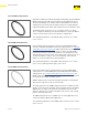


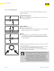
Table Of Contents
- About this Document
- Disclaimer
- Product Information
- Handling Instructions
- Installation Instructions
- Limited Warranty
- ProPress approved applications
- Minimum distance between press fittings
- ProPress standard jaws clearance requirements
- ProPress standard jaws clearance requirements between tube, wall, and floor
- ProPress compact jaws clearance requirements
- ProPress compact jaws clearance requirements between tube, wall, and floor
- ProPress rings dimensions
- ProPress rings with V1 Actuator clearance requirements
- ProPress rings with V2 Actuator clearance requirements
- ProPress rings with V1 Actuator clearance requirements between tube, wall, and floor
- ProPress rings with V2 Actuator clearance requirements between tube, wall, and floor
- ProPress rings with C1 Actuator clearance requirements between tube, wall, and floor
- ProPress XL-C rings dimensions
- ProPress XL-C rings clearance requirements
- ProPress XL-C rings clearance requirements between tube, wall, and floor
- Minimum distance between existing soldered or brazed fitting and ProPress fitting
- Minimum distance between existing ProPress fitting and soldered or brazed fitting
- Minimum insertion depths for ProPress ½" to 2" fittings
- Insertion depths for ProPress ½" to 2" no-stop couplings
- Insertion depths for ProPress ½" to 2" extended no-stop couplings
- Minimum insertion depths ProPress 2½" to 4" fittings
- Insertion depths for ProPress 2½" to 4" no-stop couplings

Product Information
18 of 44
IM-PP 724607 0320 ProPress
■ As long as the tube is properly prepped and marked
and the tting is installed according to Viega’s ProPress
Product Instructions, if there is any deection present
after the installation of the tting, the connection is
still acceptable and meets Viega’s manufacturing
specications for proper installation and warranty.
■ Deection of a press connection has no eect on the
integrity of the system, and it can be pressure tested in
accordance with the ProPress Product Instructions.
Push-Pull Method
▶ Rings = Push on press tool.
▶ Jaws = Pull on press tool.
The press tool can be feathered using the trigger as needed to apply
pulling or pushing force to control deection.
2.5.10.1 Controlling Deection
Deection while pressing can be minimized by utilizing the following
installation practices.
Alternate Press Directions
▶ Press one end of tting.
▶ Make second press on other end of tting from the opposite side.
Site conditions permitting.
Re-Press
▶ Press the tting, once on each side (that is, re-press the tting a
second time on the opposite side). Pressing the same connection
from the opposite side will usually straighten misalignment between
the tube and tting.
■ When pressing overhead piping, it may be inconvenient to alternate
sides for each press.
■ The natural weight of the piping plus pressing on opposite sides at a
45 degree angle should adequately eliminate deection.
■ This technique can also be used for any horizontal piping and also
when working above the piping.