
Installation Guide


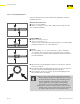
Table Of Contents
- About this Document
- Disclaimer
- Product Information
- Handling Instructions
- Installation Instructions
- Limited Warranty
- ProPress approved applications
- Minimum distance between press fittings
- ProPress standard jaws clearance requirements
- ProPress standard jaws clearance requirements between tube, wall, and floor
- ProPress compact jaws clearance requirements
- ProPress compact jaws clearance requirements between tube, wall, and floor
- ProPress rings dimensions
- ProPress rings with V1 Actuator clearance requirements
- ProPress rings with V2 Actuator clearance requirements
- ProPress rings with V1 Actuator clearance requirements between tube, wall, and floor
- ProPress rings with V2 Actuator clearance requirements between tube, wall, and floor
- ProPress rings with C1 Actuator clearance requirements between tube, wall, and floor
- ProPress XL-C rings dimensions
- ProPress XL-C rings clearance requirements
- ProPress XL-C rings clearance requirements between tube, wall, and floor
- Minimum distance between existing soldered or brazed fitting and ProPress fitting
- Minimum distance between existing ProPress fitting and soldered or brazed fitting
- Minimum insertion depths for ProPress ½" to 2" fittings
- Insertion depths for ProPress ½" to 2" no-stop couplings
- Insertion depths for ProPress ½" to 2" extended no-stop couplings
- Minimum insertion depths ProPress 2½" to 4" fittings
- Insertion depths for ProPress 2½" to 4" no-stop couplings

Handling Instructions
19 of 44
IM-PP 724607 0320 ProPress
All Viega ProPress components and associated tubing shall be free from
dirt, debris, or items that may interfere with the sealing element and the
press connection. Viega ProPress sealing elements, separator rings, and
grip rings are to be visually inspected prior to installation to ensure the
seal is intact and properly located within the tting.
3 Handling Instructions
3.1 Transport
When transporting ttings:
■ Do not pull or drag the ttings or system components along other
surfaces.
■ Secure ttings, tubing, and system components during transportation
to keep them from shifting.
■ Do not damage the protective cap on components or tube ends.
■ Do not remove protective caps until immediately before installing.
3.2 Storage
When storing materials:
■ Store ttings, tubing, and system components in a clean and dry
place.
■ Do not store components directly on the oor.
■ Provide at least three points of support for the storage of tubing.
■ Where possible, store dierent sizes separately.
■ Store small sizes on top of larger sizes if separate storage is not
possible.
■ Store ttings, tubing, and system components of dierent materials
separately to prevent contact corrosion.