
Product Specifications


Vitodens 100-W Accessories
13
Accessories for the Vitodens 100-W
Neutralization Unit for Single-Boiler
Applications
with neutralizing granulate
for Vitodens 100-W, WB1B 10-26, 10-35
Part No. 7134 231
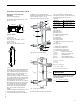
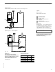
Low-Loss Header
–Type 80/50
Part No. 7134 791
(max. flow rate 17.6 GPM / 4 m
3
/h)
–Type 120/80
Part No. 7134 792
(max. flow rate 35.2 GPM / 8 m
3
/h)
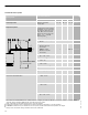
A low-loss header offers additional benefits
not provided by a pair of closely spaced
tees. Viessmann strongly recommends and
prefers the use of a low-loss header over
closely spaced tees. When used in
conjunction with the Vitodens 100-W boiler,
the low-loss header acts as hydraulic break,
decoupling boiler and system circuits from
each other (no sensor required). It is
recommended to use the low-loss header in
applications in which the total system flow
rate exceeds the maximum or falls below
the minimum flow rate of the Vitodens
100-W boiler. For maximum boiler flow
rates, see the table on page 9 in this
manual.
Viessmann strongly recommends the use of
a low-loss header in cases where the
system head and flow rates are unknown.
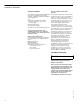
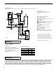
In addition, the low-loss header helps
eliminate air and debris [D] from the heating
system. See Fig. 10 and 11 for an
illustration of the principle of operation.
Product does not look exactly as illustrated.
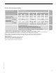
The low-loss header is available in the
following sizes. Select the size based on the
maximum system flow rate of your
application.
Model No. Max. system flow rate
Type 80/50 17.6 GPM / 4 m
3
/h
Type 120/80 35.2 GPM / 8 m
3
/h
Legend
AB Air Bleed
BR Boiler Return
BS Boiler Supply
BY Bypass (with laminar flow)
D Debris and/or air
DV Drain Valve
SR System Return
SS System Supply
TS Viessmann Temperature Sensor (not
used)
SW Sensor Well
T1 Boiler supply temperature
T2 Boiler return temperature
T3 System supply temperature
T4 System return temperature
V
primary
Boiler circuit flow rate
V
secondary
Heating circuit flow rate
V
bypass
Bypass flow rate
Q
primary
Heat supplied by boiler
Q
secondary
Heat consumed by system
V
primary
< V
secondary
T1 > T3
T2 = T4
Q
primary
= Q
secondary
T1 ± 176°F / 80°C
V
secondary
=V
primary+
V
bypass
When installing a low-loss header, system
mixed supply temperature (T3) must be
calculated as follows:
T3=
T1 × V
primary
+T4 V
bypass
V
secondary
5
3
6
9
2
7
7
v
1
.
5
310 mm
DN 40
145 mm
Fig. 8
Fig. 9
DV
BS
SS
SR
BR
TS
BY
AB
D
SW
Fig. 10
Low-loss header design
T1
T2
V
primary
V
secondary
T3
T4
T4V
bypass
Fig. 11
Principle of Operation
IMPORTANT