
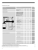
Product Specifications


Standard Equipment/How the Vitodens 100-W Operates.../
Installation Examples
14
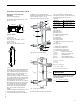
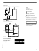
Standard Equipment
The Vitodens 100-W gas-fired condensing
boiler with Inox-Radial heat exchanger
surfaces, modulating stainless steel MatriX
cylinder gas burner
c/w
H installation fittings with 30 psig
pressure relief valve, air vent and
pressure gauge
H two fill/drain valves
H all mounting hardware
The boiler comes fully piped and prewired.
Venting material (coaxial) is to be
supplied by Viessmann only. Side wall
vent installations must include Viessmann
protective screen!
Wall mounting componentry
The following wall mounting components
are supplied with the Vitodens 100-W
boiler:
H Mounting bracket
H Mounting bolts
H Installation fittings
H Screws for mounting bracket on
– wood studs (2” x 4”)
– metal studs
– brick/concrete wall
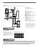
How the Vitodens 100-W boiler
operates...
The Vitodens 100-W boiler uses a premix
combustion system, which is designed to
deliver a certain air-gas mixture to the
burner for complete combustion. The gas
is injected upstream of the blower. The
burner and heat exchanger are part of a
forced-draft design.The benefits of
forced-draft systems are lower
component temperatures, direct air-fuel
connection (premix) for improved mixing,
and longer service life of the boiler due to
mild to moderate ambient conditions.
The MatriX cylinder burner, blower and
the combination gas valve are factory
calibrated and pre-adjusted. A pneumatic
link between combustion air and gas
flows guarantees optimal boiler
performance at all firing rates. Blower
speed is automatically increased or
decreased based on heat demand,
thereby regulating the amount of
combustion air drawn. The pneumatic link
between air and gas introduces the
required amount of gas for optimal
combustion to meet the current heat
demand, based on a linear relationship
between ∆
∆∆
∆ P air and ∆
∆∆
∆ P gas.
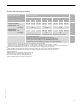
Installation Examples
The examples on the following pages
depict possible piping layouts of the
Vitodens 100-W boiler.
Please note that the following examples
are simplified conceptual drawings only!
Piping and necessary componentry must
be field verified. A low water cut-off
(LWCO) must be installed where required
by local codes. Proper installation and
functionality in the field is the
responsibility of the heating contractor.
5
3
6
9
2
7
7
v
1
.
5
IMPORTANT