
Product Specifications


Installation Examples
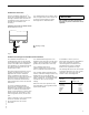
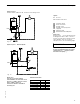
15
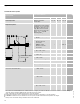
System Layout 1
Vitodens 100-W, WB1B 10-26, 10-35 with one heating circuit
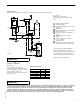
System Layout 1 - Alternate Option
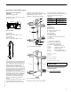
Legend
AV Air vent
PRV Pressure relief valve
Vitodens 100-W
Room thermostat
Heating circuit
Heating circuit pump (field
supplied)
Expansion tank
Pressure Activated By-Pass
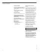
Please note:
Heating circuit C in the examples should
be designed to 30ºF to 40ºF / 16.7ºC to
22.2ºC. For lesser delta T design, system
layout designer must use one of the
examples (3 or 4) on the following pages.
Ensure that a pressure activated
by-pass is installed if there are system
component(s) in C that may isolate
the flow to the pump D.
Please note!
The use of a low-loss header is
recommended if the water flow rate is
less than 1.7 GPM / 400 ltr/h or more
than 6.2 GPM / 1400 ltr/h.
The low-loss header is available as
accessory part.
Maximum Flow Rates
Model WB1B 10-26 10-35
∆
∆∆
∆
t
Output
Btu/h
83,000 108,000
30 ºF rise (GPM) 5.5 ----
35 ºF rise (GPM) 4.7 6.2
40 ºF rise (GPM) 4.2 5.4
5
3
6
9
2
7
7
v
1
.
5
PRV
AV
*
Fig. 12
F
T--T
PRV
AV
*
F
i
g
.
1
3
F
T--T
IMPORTANT