Installation and Service Instructions Please file in Service Binder for use by heating contractor Vitotronic 300, Model GW2 Outdoor-reset logic digital boiler and heating circuit control unit VITOTRONIC 300 IMPORTANT Certified as a component part of Viessmann boilers only 5285 941 v1.5 05/2012 Read and save these instructions for future reference.
General information Safety, Installation and Warranty Requirements Please ensure that this manual is read and understood before commencing installation. Failure to comply with the issues listed below and details printed in this manual can cause product/property damage, and/or severe personal injury. Ensure all requirements below are understood and fulfilled (including detailed information found in manual subsections).
General information Product Information Vitotronic 300, Model GW2 For installation in or mounting on Viessmann boilers only. Applicable to the following control units Order No. 7134 555, 7143 156, 7511 362 from Serial No. 7143 000 Order No. 7134 555, 7143 156, 7511 362 from Serial No. 7187 101 5285 941 v.1.5 Order No. 7134 555, 7143 156, 7511 362 from Serial No.
Index Page General information Product information Heating system types Installation .......................................................................... 2 ............................................................................. 3 Safety Requirements System types for modulating boilers ........................................... 6 System types for condensing boilers .......................................... 12 .............................................. 18 ..................
Index Page Scanning service information Overview of service levels ............................................................... ................... 73 ....................................... 77 Temperatures, boiler coding cards and scanning Scanning operating status information ......................... 78 ........................................................................ 79 .................................................................................................
Heating system types Heating system types for modulating boilers System type 1 – Single-boiler system with shunt pump for raising the return temperature in conjunction with Vitorond 200, VD2 C 6 20 20 52 52 T2 T1 A*1 plugs ! Outdoor temperature sensor ? M2 Supply temperature sensor, mixing valve circuit 2 ? M3 Supply temperature sensor, mixing valve circuit 3 § Boiler temperature sensor % DHW tank temperature sensor aJA Temperature sensor T1 aJB Temperature sensor T2 sÖ A1 Close mixing valves wit
Heating system types Heating system types for modulating boilers Possible applications Heating systems with manifold arranged close to the boiler. The boiler water flow is required to be reduced. Please note: This circuit diagram represents a recommendation only. It is the responsibility of the customer and/or the heating contractor to check that this recommendation is complete and fully functional. Three-phase equipment must be connected via additional power contactors.
Heating system types Circuit Diagram 1 Single-boiler system with Therm-Control and three-way mixing valve in conjunction with Vitorond 200, VD2A A Heating circuit with mixing valves B DHW tank ?M3 § % aJA fÖ Outdoor temperature sensor Flow temperature sensor, mixing valve Flow temperature sensor, mixing valve Boiler water temperature sensor DHW tank temperature sensor Therm-Control temperature sensor sÖM2 sÖM3 sÖA1 sA sK Heating circuit pump, mixing valve Heating circuit pump, mixing valve Closing the
Heating system types Circuit Diagram 1 (continued) Wiring diagram Wiring of the Therm-Control in heating systems with heating circuit control units are not connected to the boiler control unit via the LON. Required coding: Change “4C” to “2” - use the plug-in connector 20 A1 to close the downstream mixing valve. Change “0D” to “1” - the Therm-Control acts on the mixing valve of the downstream heating circuits (for Vitotronic 200 and 300, delivered condition). 5285 941 v1.
Heating system types Heating system types for modulating boilers (continued) System type 2 – Single-boiler system with shunt pump and return valve for raising the return temperature in conjunction with Vitorond 200, VD2 M3 A1 2 20 52 52 1 28 21 5 143 146 M2 2 M3 2 20 20 52 52 T2 T1 *1 A plugs ! Outdoor temperature sensor ? M2 Supply temperature sensor, mixing valve circuit 2 ? M3 Supply temperature sensor, mixing valve circuit 3 § Boiler temperature sensor % DHW tank temperature sensor
Heating system types Heating system types for modulating boilers Possible applications Heating systems with distributor arranged close to the boiler. The boiler water flow is required to be reduced. Please note: This circuit diagram represents a recommendation only. It is the responsibility of the customer and/or the heating contractor to check that this recommendation is complete and fully functional. Three-phase equipment must be connected via additional power contactors.
Heating system types Heating system types for condensing boilers System type 3 – Single-boiler system with Vitocrossal 300 A1 M2 M3 20 2 20 52 2 20 52 C 1 28 21 5 C M2 2 M3 2 20 20 52 52 B D A plugs ! Outdoor temperature sensor ? M2 Supply temperature sensor, mixing valve circuit 2 ? M3 Supply temperature sensor, mixing valve circuit 3 § Boiler temperature sensor % DHW tank temperature sensor sÖ A1 Heating circuit without mixing valve (if installed) sÖ M2 Heating circuit pump, mixing val
Heating system types Heating system types for condensing boilers Please note: This circuit diagram represents a recommendation only. It is the responsibility of the customer and/or the heating contractor to check that this recommendation is complete and fully functional. Three-phase equipment must be connected via additional power contactors. (continued) The Vitocrossal 300 is operated with modulating boiler water temperature by means of the outdoor re-set boiler control unit.
Heating system types Heating system types for condensing boilers (continued) System type 4 - Single-boiler system with Vitocrossal 300 with several heating circuits and one modulating supply temperature heating circuit C D M2 2 M3 2 20 20 52 52 E M3 2 F 20 M3 2 20 52 2 20 52 143 146 41 90 G A Boiler with Vitotronic 300 B Domestic hot water tank C Heating circuit with mixing valve D Modulating supply temperature heating circuit or E Underfloor heating circuit F High limit thermostat (max
Heating system types Heating system types for condensing boilers Possible applications For heating circuits with different temperatures. Please note: This circuit diagram represents a recommendation only. It is the responsibility of the customer and/or the heating contractor to check that this recommendation is complete and fully functional. Three-phase equipment must be connected via additional power contactors.
Heating system types Heating system types for condensing boilers System type 5 – Single-boiler system with Vitocrossal 200 plugs ! Outdoor temperature sensor ? M2 Supply temperature sensor, mixing valve circuit 2 ? M3 Supply temperature sensor, mixing valve circuit 3 § Boiler temperature sensor % DHW tank temperature sensor sÖ A1 Heating circuit without mixing valve (if installed) sÖ M2 Heating circuit pump, mixing valve circuit 2 sÖ M3 Heating circuit pump, mixing valve circuit 3 sA Circulation pump fo
Heating system types Heating system types for condensing boilers Please note: This circuit diagram represents a recommendation only. It is the responsibility of the customer and/or the heating contractor to check that this recommendation is complete and fully functional. Three-phase equipment must be connected via additional power contactors. (continued) The Vitocrossal 200 is operated with modulating boiler water temperature by means of the outdoor re-set boiler control unit.
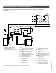
Installation Overview of electrical connections M3 M2 M3 M2 M3 M2 145 145 1 17 B 17 A 5 3/2 15 143 146 Mixing valve extension circuit board ? M2/M3 Supply temperature sensor sÖ M2/M3 Heating circuit pump gS M2/M3 Mixing valve motor 18 151 28 21 52 A1 20 A1 29 50 40 156 156 90 41 150 Low-voltage motherboard ! Outdoor temperature sensor (ATS) § Boiler temperature sensor (BTS) % DHW tank temperature sensor (STS) aG Flue gas temperature sensor (AGS) (accessory) aJA Therm-Control temperature sensor or re
Installation 5285 941 v.1.
Installation 5285 941 v.1.
Installation Routing and strain relief of cables 1. Run the cables from the connection enclosure into the control unit. 2. Apply strain relief to cables (see below). Cables with moulded strain relief clamp Connect cable and strain relief clamp. OR 5285 941 v.1.5 Fasten cable to the cable lead with cable tie.
Installation Inserting the boiler coding card CAUTION For matching the operation of the control unit to the boiler, only the boiler coding card which is supplied as part of the standard delivery of the boiler may be used. Only use the boiler coding card included with the boiler. Boiler Coding card Part No. Vitocrossal 300, type CT3 1040 7820 144 Vitorond 200, VD2 / VD2A 1020 7820 142 Vitocrossal 200 CM2 1041 7820 145 5285 941 v.1.5 1.
Installation Adjustment of the fixed high limit (if required) The fixed high limit is supplied with a factory setting of 110°C / 230°F. A Adjustment to 99°C / 210°F ¨ Disconnect power to control and burner! 1. Unclip the fuse box and swing upwards. 2. Turn the slotted screw on the rear of the fixed high limit until the slot points to 99°C / 210°F (once adjusted, the fixed high limit cannot be reset to 110°C/ 230°F). 3. 3. Re-fit the fuse box.
Installation Adjustment of the adjustable high limit (if required) The adjustable high limit is supplied with a factory setting of 95°C. Adjustment to 100°C / 212°F A 1. Using a suitable screwdriver, lever out and remove the selector knob ”R” behind the hinged cover. 3. 2. 2. Using a pair of pointed pliers, break off the cams identified by the shaded areas in the Fig. from the stop dial. A 75 to 100°C 167 to 212°F 3.
Installation Connection of the outdoor temperature sensor The outdoor temperature sensor should be mounted 2 to 2.5 metres / 6.5 to 8 ft above ground level on the north or north-west facing wall of the building. In the case of multi-storey buildings, it should be mounted in the upper half of the second storey. Make sure that the sensor is not located over windows, doors and air vents, nor immediately beneath a balcony or guttering. Do not paint over the outdoor temperature sensor housing. 1.
Installation Connection of the boiler temperature sensor The sensor measures the boiler water temperature. The boiler temperature sensor is installed at the same time as the boiler insulation. 3 Check the sensor 1. Disconnect plug § in the terminal compartment of the boiler control. 2. Measure resistance of sensor at terminals ”1” and ”2” of the plug. Resistance in Ω 40 / 104 50 / 122 60 / 140 578 597 616 3. Compare the value measured with the current temperature.
Installation Connection of the DHW tank temperature sensor The sensor measures the domestic hot water tank temperature. Heating systems with domestic hot water heating (single-boiler systems only) 1. Install the DHW tank temperature sensor. 5 See Installation Instructions for domestic hot water tank. Please note: When installing the sensor in DHW tanks of other makes, make sure that the sensor is pressed against the sensor well of the DHW tank by means of a suitable device. 2.
Installation Connection of the return temperature sensor Strap-on temperature sensor and immersion temperature sensor For measuring the boiler return temperature. Electrical connection The sensor is inserted in socket ”17A” or ”17B” on the boiler control. 17A or 17B Check the sensor 1. Disconnect plug aJA or aJB in the terminal compartment of the boiler control. 17A or 17B 2. Measure resistance of sensor at terminals ”1” and ”2” of the plug. Resistance in Ω 30 / 86 40 / 104 60 / 140 569 592 643 3.
Installation Connection of the flue gas temperature sensor (VD2/VD2A/CT3 only) The sensor measures the flue gas temperature and monitors the selected limit value. Electrical connection The sensor is inserted in socket ”15” on the boiler control. Check flue gas temperature sensor 1. Disconnect plug aG in the terminal compartment . 2. Measure resistance of sensor at terminals ”1” and ”2” of the plug. 1020 980 Flue gas temperature in °C / °F Resistance in Ω 180 / 176 160 / 320 200 / 392 650 800 880 3.
Installation Connection of the Pumps (VD2/VD2A/CT3 only) Available pump connections sÖ A1/M1Heating circuit high temperature (without mixing valve) Terminals 5 - L, - G , - N sA Circulation pump for heating up the domestic hot water tank Terminals 4 - L, - G , - N sL Shunt pump, boiler circuit pump Terminals 6 - L, - G, - N.
Installation Connection of the Pumps (CM2 only) Available pump connections sÖ A1/M1Heating circuit high temperature (without mixing valve) Terminals 7 - L, - G , - N sA Circulation pump for heating up the domestic hot water tank Terminals 6 - L, - G , - N sL Shunt pump, boiler circuit pump Terminals 8 - L, - G, - N.
Installation Connection of boiler return mixing valve or modulating valve actuator (VD2/VD2A/CT3 only) 1 120V or 24V valve adaptor 1 120V valve adaptor 1 24V valve adaptor 2 DIN rail in connection enclosure 2 120V valve actuator 2 24V valve actuator 3 aBH Terminals 120V valve adaptor Rated voltage: 120 VAC Rated current: max. 0.1 FLA Recommended connection wire size: AWG 14 Part No.: 7134 560 24V valve adaptor Rated voltage: 24 VAC Rated current: max. 0.
Installation Connection of Boiler Return Mixing Valve or Isolation/Modulating Valve actuator (CM2 only) 10 11 12 1 120V or 24V Valve Adaptor 1 120V Valve Adaptor 1 24V Valve Adaptor 2 Junction box 2 120V valve actuator 2 24V valve actuator 3 120V L out power supply 120V Valve Adaptor Rated voltage: 120 VAC Rated current: max. 0.1 FLA Recommended connection wire size: AWG 14 Part No. 7511367 24V Valve Adaptor Rated voltage: 24 VAC Rated current: max. 0.
Installation Making Space for Accessory Adaptors on the DIN Rail (CM2 only) 1. Push up on the bottom front of the DIN rail clamp to remove and set aside. 2. Using a flat head screwdriver, remove the 4 ’spare’ DIN terminals 23, 24, 25 and 26 one at a time. Place the screwdriver between the rail and the base of the terminal and turn the screwdriver clockwise . Discard the removed terminals. 3.
Installation Connections to terminal aBÖ (VD2/VD2A/CT3 only) External shut-off 1. Remove jumper between terminals 16 and 17. 2. Connect dry contact. Controlled switch-off takes place when the contact is opened. WARNING The terminals should be used for safety switch-off purposes only (e.g. through a high limit thermostat). Start at page 52 for details of controlled switch-off.
Installation Connection of the compiled failure alarm indicator (VD2/VD2A/CT3 only) A Rated voltage: 120 VAC 60 Hz Rated current: max. 2 FLA Recommended connection wire size: AWG 14 1. Disconnect power to control and burner. 2. Connect the compiled failure alarm as shown in the diagram. A Connect terminal strip in connection enclosure of boiler control. B Visual ond/or audible alarm device (120 VAC). 5285 941 v.1.
Installation Connection of the compiled failure alarm indicator (CM2 only) 9 A Rated voltage: 120 VAC 60 Hz Rated current: max. 2 FLA Recommended connection wire size: AWG 14 1. Disconnect power to control and burner. 2. Connect the compiled failure alarm as shown in the diagram. A Connect terminal strip in connection enclosure of boiler control. B Visual ond/or audible alarm device (120 VAC). 5285 941 v.1.
Installation Connection of external equipment to terminal aVD External changeover of the heating program/”Open mixing valves” A Connect floating contact to terminals ”1” and ”2”. The manually preselected heating program can be changed over (see table) and the mixing valves opened via the contact. B Via coding address ”9A” the function ”Open mixing valves” and via coding address ”91” the changeover of the heating program can be assigned to the heating circuits.
Installation Connection of external equipment to plug aVH External demand B A Connect floating contact to terminals ”2” and ”3”. The burner of the boiler is switched in on a load-dependent basis when the floating contact is closed. The boiler water temperature is limited by the preset max. boiler water temperature or by the value set on the mechanical adjustable high limit. The required boiler set-point value is set via the coding address ”9b”.
Installation Connection of external controls Operation with two-stage burner Settings on the control unit The settings for the fixed high limit and the other settings are dependent on the safety equipment installed in accordance with applicable codes.
Installation Connection of external controls (VD2/VD2A only) (continued) Modulating boilers – operation with external modulation controller 1st stage burner fA from Vitotronic. Plug lÖ from Vitotronic via modulation controller (BAS). On the bulding automation unit with modulation controller set the minimum temperatures 5°C / 9°F above the minimum boiler water temperature of the boiler. Boiler activation, isolation valve open or closed Connect dry contact at terminals ”2” and ”3” of the plug aVH.
Installation Connection of external controls (VD2/VD2A only) (continued) Modulating boilers – operation with external modulation controller (continued) Settings on the control unit The settings for the fixed high limit and the other settings are dependent on the safety equipment installed in accordance with applicable codes.
Installation Connection of external controls (CT3 only) (continued) Vitocrossal 300 – operation with external modulation controller 1st stage burner fA from Vitotronic 100. Connection lÖ from Vitotronic has no function. Connection lÖ from building automation system to the burner. 1st stage burner activated by the modulation controller via connection aVH. Boiler activation, isolation valve open or closed Connect dry contact at terminals ”2” and ”3” of the plug aVH.
Installation Connection of external controls (CT3 only) (continued) Vitocrossal 300 – operation with external modulation controller (continued) Settings on the control unit The settings for the fixed high limit and the other settings are dependent on the safety equipment installed in accordance with applicable codes.
Installation Connections of combustion air device adaptor (VD2/VD2A/CT3 only) Connection of the Combustion Air Device Adaptor 1. Disconnect power to control and burners. 2. Install Combustion Air Device Adaptor, Part No.: 7134 563 on DIN Rail inside connection enclosure (refer to installation manual of Combustion Air Device Adaptor). 3. Remove jumper between terminals 16 and 17. 4. Make connection as shown in the diagram.
Installation Connection of Combustion Air Device (CM2 only) Connection of the Combustion Air Device Adaptor Connection of the combustion air blower to adaptor 1. Disconnect power to control and burners. Rated voltage: 120 VAC Rating current: max 5 FLA Recommended connection wire size: AWG 14 2. Install Combustion Air Device Adaptor, Part No. 7134 563 on DIN Rail inside the boiler junction box (refer to installation manual of Combustion Air Device Adaptor). D 3.
Installation Connection of combustion air device (continued) Connection of the combustion air damper See damper manual for correct installation. E Note: Assure that the combustion air damper is suitable for this application. 1. Disconnect power to control and burner. 2. Make connection as shown in the diagram.
Installation Flue Gas Temp. Switch (optional for CM2 equipped with SS flue collector) (CM2 only) 1. Disconnect power. CAUTION Please note that the diagram shown is only a simplified conceptual drawing of a flue gas temperature switch. Refer to the manual specific to the device for interconnection details. 2. Remove 150 plug from the Vitotronic control. 3. Remove STB jumper from plug 150. 4. Using 14 AWG (field supplied) connect STB(Left), STB(Right) and ground to the DIN rail as shown in the diagram.
Installation Connection of low water cut-off device (VD2/VD2A/CT3 only) 1.Remove jumper between terminals 12 and 15. 2.Make connection as shown in diagram. CAUTION Please note that the diagram at left is only a simplified conceptual drawing of a typical low water cut off (LWCO) device. Refer to the manual specific to the device for interconnection details. aBH Power supply for accessories. 5285 941 v.1.5 aBÖ Connection for external equipment.
Installation Connection of Low Water Cut-off Device (CM2 only) 1. Remove jumper between terminals 21 and 22. 2. Make connection as shown in diagram. CAUTION 5285 941 v1.5 Please note that the diagram shown is only a simplified conceptual drawing of a typical low water cut-off (LWCO) device. Refer to the manual specific to the device for interconnection details.
Installation Burner connection, Burner control wiring (VD2/VD2A/CT3 only) For burners with plug-in connection A The burner cables are included in the standard delivery of the Vitotronic. Connect the burner in accordance with applicable codes. ATo boiler control unit BTo burner Terminal codes 2. Connect plugs fA and plug lÖ to respective counter plugs in boiler control unit.
Installation Burner Connection, Burner Control Wiring (VD2/VD2A/CT3 only) (continued) CAUTION This is a generic connection drawing only! Follow the burner manufacturer’s connection drawings for Viessmann controls. Write the terminal numbers or markings on the drawing for future reference. Plug connection located on the DIN rail.
Installation Burner Connection, Burner Control Wiring (VD2/VD2A/CT3 only) (continued) Burner motor power supply connection (continued) For burners with 240 VAC, 1PH power supply and connection in conduit. See burner manual for correct fuse and wire gauge sizing, and specific connections for Viessmann controls. 1.Disconnect power to burner and boiler control. 2.Connect 240 VAC power to the terminals 21, 22 and 23 on the DIN rail inside the connection enclosure.
Installation Burner Connection, Burner Control Wiring (VD2/VD2A/CT3 only) Burner motor power supply connection (continued) For burners with 3PH 208, 460 or 575V power supply. (continued) See burner manual for correct fuse and wire gauge sizing, and specific connections for Viessmann controls. 1.Disconnect power to burner and boiler control. 2.Connect 3PH power to the terminals 21, 22, 23 and 24 on the DIN rail inside the connection enclosure. Provide fuseable disconnect means according to local codes. 3.
Installation Power Supply Connection, Boiler Control (VD2/VD2A/CT3 only) Legend L: Line N: Neutral G: Ground A Power supply 120 VAC, 1 PH . Provide disconnect means and overcurrent protection as per local codes B Terminals [40] C Connection enclosure 1. Ensure that the main power supply to the control contains overcurrent protection with a maximum rating of 15 A and 2 pole disconnect. CAUTION The control must be grounded. Ensure that “L”, “N” and “G” are not interchanged. 5285 941 v1.5 2.
Installation Burner Connection, Burner Control Wiring (CM2 only) For burners with plug-in connection A The burner cables are included in the standard delivery of the Vitotronic. Connect the burner in accordance with applicable codes. ATo boiler control unit BTo burner interface 1.Disconnect power to burner and boiler control. Terminal codes 2. Connect plugs fA and plug lÖ to respective counter plugs in boiler control unit.
Installation Mounting the Front Part of the Control Unit (VD2/VD2A/CT3 only) 1. 7. 8. 1. Position the front part of the housing and clip hinges to counter-parts on main housing. 2. Release the stay bar, open it up and lock in position at point A. 6. 3. Insert the flat cable from the Optolink into plug ”X20”. 4. Insert the plug of the programming unit into socket ”X10”. Use cable guides in cover for routing. 5. Engage the stay bar in the front housing. 6. Close the front of the housing. 2. A 7.
Installation Mounting the Front Part of the Control Unit (VD2/VD2A/CT3 only) 1. 7. 8. 1. Position the front part of the housing and clip hinges to counter-parts on main housing. 2. Release the stay bar, open it up and lock in position at point A. 6. 3. Insert the flat cable from the Optolink into plug ”X20”. 4. Insert the plug of the programming unit into socket ”X10”. Use cable guides in cover for routing. 5. Engage the stay bar in the front housing. 6. Close the front of the housing. 2. A 7.
Installation Opening the Control Unit (VD2/VD2A/CT3 only) 1. Remove the cover of the connection enclosure. 2. Unscrew the screws from the front housing. 2. 3. Swing up the front part of the control housing. 4. Position the stay bar so that it supports the front housing. 1. 3. 5285 941 v1.5 4.
Installation Control and Junction Box Installation Instructions (for CM2 only) 1. Route cables and capillaries from control through the opening in the control panel. Guide the cables to the junction box through the opening in the rear panel and along the top rail to the control. Secure all cables to the rail with cable ties. Insert capillaries into the sensor well. Note: Never allow cables to come in contact with hot metal components. WARNING Do not bend or kink the capillaries.
Installation Mounting the Front Part of the Control Unit (CM2 only) 1. Position the front part of the housing and clip hinges to counter-parts on main housing. 2. Release the stay bar, open it up and lock in position at point A. A 3. Insert the flat cable from the Optolink into plug ”X20”. 4. Insert the plug of the programming unit into socket ”X10”. Use cable guides in cover for routing. 5. Engage the stay bar in the front housing. 6. Close the front of the housing. 7.
Installation Opening the Control Unit (CM2 only) 1. Remove the control cosmetic cover . 2. Unscrew the screws from the front housing. 3. Swing up the front part of the control housing. 5285 941 v1.5 4. Position the stay bar so that it supports the front housing.
Start-up Procedure (overview) Page 11. Controls and indicators . . . . . . . . . . . . . . . . . . . . . . . . . . . . . . . . . . . . . . . . . . . . . . . . . . . . . . . . . . . . . . . . . . . . . . . . . . . 64 ........................................... 64 ................................................................... 65 12. Check assignment of heating circuits 13. Check the fixed high limit 14. Select the language (if required) .......................................................
Start-up Steps 1. Controls and indicators Override switch Heating circuit selection Display window Normal room temperature Heating programs Adjustable high limit Kesseltemperatur Mo Fixed high limit reset button Control on/off switch Fuses TÜV TEST button Energy saving mode Party mode Hinged cover of programming unit Operating status indicator (green) Fault indicator (red) 2. Check assignment of heating circuits Boiler temperature Mo 5285 941 v.1.
Start-up Steps (continued) 3. Check the fixed high limit The check is made via the ”TÜV TEST” button (see page 64). When making the check, the ” TÜV TEST” button must be kept continuously pressed. A minimum supply is required during the check. The minimum amount of recirculated water should be 10% of the amount recirculated at the rated load. The amount of heat consumed should be reduced as far as possible. The adjustable high limit ”R” is bridged.
Start-up Steps (continued) 5. Integrate the control unit in the LON BUS system in conjunction with Vitotronic 200-H The LON communication module (accessory) must be inserted (see page 96). Set the LON participant number Set the LON participant number via coding address ”77” in coding 1 (factory setting: ”77: 1”). See page 114 for coding 1. Please note: The same number must not be assigned twice within a LON BUS system.
Start-up Steps (continued) 6. Carry out participant check The participant check is used to verify the communication of the system units connected to the fault manager. Requirements: The control unit must be coded as the fault manager (coding ”79: 1”) The LON participant number must be coded in all control units The participant list must be updated in the fault manager User check simultaneously 1. Press w and for approx. 2 seconds. The participant check is initiated.
Start-up Steps (continued) 7. Match the control unit to the system type Set the following coding addresses in Coding 2: ”00” System type ”02” Burner type ”03” Oil or gas-fired operation ”0C” Return temperature raising ”4C” Plug sÖ function ”4d” Plug sL function ”4E” Plug gS function See page 116 for coding 2. 8. Check outputs (actuators) and sensors Carry out relay test Relay test 1. Press and simultaneously for approx. 2 seconds. 2. Select relay outputs with the button. 3. Press .
Start-up Steps (continued) Check sensors 1. Press . Relaistest 2. Scan actual temperatures with or . 3. Press . Scanning of operating status information is activated (see page 77). Scanning is terminated. 9. Match the coding addresses Match control unit to modulating burner Please note: The burner must be adjusted. In order to achieve a wide modulation range, the minimum output should be set as low as possible (take chimney/flue system into account). 1. Start up the burner. Burner mod. open 2.
Start-up Steps (continued) 9. Match the coding addresses (continued) 10. Set the established values in coding Level 1. See page 114 for coding 1. Address Setting of 05 the partial output (see point 8) as a percentage proportion of the max. output; e.g. partial output: 170 kW max. output: 210 kW 170 kW x100 % = 81 % 210 kW 08 units and tens digits of the maximum output established in point 4: e.g. max. output: 210 kW – here set: 10 09 hundreds digit of the maximum output established in point 4: e.
Start-up Steps (continued) 10. Adjust the heating curves The heating curves represent the relationship between the outdoor temperature and the boiler water or supply temperature. Put simply: The lower the outdoor temperature, the higher the boiler water temperature. In turn, the room temperature is dependent on the boiler water temperature. 2.4 2.6 3.4 3.2 3.0 2.8 Slope 2.2 2.0 1.8 Boiler water = flow temperature in °C 1.6 1.4 1.
Scanning service information Overview of service levels Button combination To exit Page Temperatures, boiler coding cards and scans Press 9 and rw simultaneously for approx. 2 seconds Press “OK” 73 Relay test Press 9 and “OK” simultaneously for approx. 2 seconds Press “OK” 68 Participant check (in conjunction with LON) Press w and “OK” simultaneously for approx. 2 seconds Press w and “OK” simultaneously for approx.
Scanning service information Temperatures, boiler coding cards and scans Outdoor temp. damped -5 1. Press 9 and rw simultaneously for approx. 2 seconds. Access diagnosis level. 2. Select the required data for scanning with the or button. 3. Press . Exit diagnosis level. The following values can be scanned depending on the system equipment installed: Damped outdoor temp. Current outdoor temp. The damped outdoor temperature can be reset to the current outdoor temperature by pressing D.
Scanning service information Temperatures, boiler coding cards and scans (continued) Scan 1 Scan 1 8 8 8 8 8 8 Free Free 0 1 to F KM BUS participant No participant connected Number of participants (e.g.
Scanning service information Temperatures, boiler coding cards and scans (continued) Scan 2 Scan 2 8 8 8 8 8 0 to F 8 0 to F Software version Plug-in adaptor for external safety equipment Software version Extension kit for mixing valve circuit M3 Free 0 to F 0 to F 0 to F Software version Extension kit for mixing valve circuit M2 Software version Programming unit of control unit Software version Control unit Scan 3 Scan 3 8 8 8 8 8 8 0 to F Software version Remote control for mix
Scanning service information Temperatures, boiler coding cards and scans (continued) Scan 4 Scan 4 is not assigned.
Scanning service information Scanning operating status information 1. Press . Outdoor temperature 12 Operating status scanning mode is activated. 2. Select the required operating status data for scanning with the or button. 3. Press . Exit the operating status scanning mode.
Scanning service information Scanning and resetting the ”Service” display When the limit values selected via coding addresses ”1F”, ”21” and ”23” (see page 120) are reached, the ”Service” display flashes on the programming unit. Please note: If a service is carried out before ”Service” is displayed, set the coding address ”24: 1” and then coding address ”24: 0”. Press . Service scan is activated. Service MFlue gas temperature °C 220 Scan the service messages with the or button.
Troubleshooting Troubleshooting steps Diagnosis 1. Establish fault message or ascertain behaviour of system 2. Look for the corresponding cause of the fault in the diagnosis tables Please note: Retrieve fault codes from the fault memory 3. Establish the action required in the table 4. Correct the fault 5285 941 v.1.
Troubleshooting Diagnosis Faults with fault display on the programming unit Fault 57 Fr Fault Mo 1 w A 57 ºC Outdoor sensor DBG- 1 1 10 1 The meaning of the fault code is explained in the table on page 81 onwards. Search fault 1. Press . The fault can be acknowledged by pressing . The fault message in the display 1 is blanked out; the red fault indicator 2 continues to flash. The central fault indicator connected to plug gÖ is switched off.
Troubleshooting Diagnosis (continued) 5285 941 v.1.5 Faults with fault display on the programming unit (continued) Fault code in display Behaviour of system Cause of fault Action 0f Controlled operation Service required ”0F” is only displayed in the fault history Carry out maintenance Please note: After carrying out maintenance, set coding ”24: 0”.
Troubleshooting Diagnosis (continued) Faults with fault display on the programming unit (continued) Fault code in display Behaviour of system Cause of fault Action 60 Boiler with maximum temperature No output reduction Return control open Short circuit Temperature sensor aJA Check temperature sensor (see page 102) 68 Boiler with maximum temperature No output reduction Return control open Open circuit Temperature sensor aJA Check temperature sensor (see page 102) 70 Shunt pump ON conti
Troubleshooting Diagnosis (continued) 5285 941 v.1.5 Faults with fault display on the programming unit (continued) Fault code Behaviour of system in display Cause of fault Action aa Controlled operation Therm-Control configuration fault: plug aJA of Therm-Control temperature sensor not inserted Insert plug aJA On Vitocrossal: Check that coding ”0d: 0” is set.
Troubleshooting Diagnosis (continued) Fault code Behaviour of system in display Cause of fault Action c1 Boiler cools down External safety equipment Check connection of plug aBÖ Check external safety equipment (see page 40) c2 Controlled operation Open circuit KM-BUS to solar control Check KM-BUS connection and solar control. Without solar control, set coding address “54: 0” c4 Controlled operation Fault Input module 0-10V Check all connections, cables etc.
Troubleshooting Diagnosis (continued) Faults with fault display on the programming unit (continued) Fault code Behaviour of system in display Cause of fault Action dc Controlled operation without influence of room temperature Short circuit Room temperature sensor, mixing valve circuit M3 Check room temperature sensor (see page 112) dd Controlled operation without influence of room temperature Open circuit Room temperature sensor, system circuit A1 Check room temperature sensor (see page 112)
Functional description Boiler temperature control Brief description The boiler water temperature is controlled by switching the burner stages or modulation on and off.
Functional description Heating circuit control Brief description The control unit has control loops for a system circuit and two mixing valve circuits. The supply temperature set-point value is determined by the outdoor temperature, the desired room temperature, the operating mode and the heating curve. The supply temperature of the mixing valve circuits is controlled by opening and closing the mixing valves in steps.
Functional description Heating circuit control (continued) Functions (continued) Extended summer energy saving function The heating circuit pump can be switched off If the outdoor temperature exceeds a value preselected via coding address ”A6” If the set-point room temperature is reduced via coding address ”A9” In conjunction with mixing valve circuit: If the mixing valve has been closed for longer than 12 minutes (mixing valve energy saving function, coding address ”A7”) Slab curing function (only in
Functional description Heating circuit control (continued) Functions (continued) Upper limit of control range Lower limit of control range Electronic maximum limit Setting range: 1 to 127°C / 34 to 260°F. Change via coding address ”C6”. Electronic minimum limit Setting range: 1 to 127°C / 34 to 261°F. Change via coding address ”C5”. Please note: The maximum limit does not replace the limit thermostat required for underfloor heating systems.
Functional description DHW tank temperature control Brief description The DHW tank temperature control is a constant value control. It operates on the basis of switching the circulation pump for heating the DHW tank on and off. The switching differential is ±2.5°C / 4.5°F. During DHW tank heating, a constant maximum boiler water temperature is set and space heating is switched off (DHW tank priority control optional).
Functional description DHW tank temperature control (continued) Control sequence DHW tank temperature falls DHW tank temperature rises (Set-point value –2.5 °C / 4.5 °F, selectable via coding address ”59”) The desired boiler water temperature is set 20 K higher than the DHW temperature set-point value (selectable via coding address ”60”). (Set-point value +2.5 / 4.5°F) The boiler water temperature set-point value is reset to the weathercompensated value.
Additional information Overview Page Technical data .................................................................................................................................................................. 93 System components Line-voltage motherboard . . . . . . . . . . . . . . . . . . . . . . . . . . . . . . . . . . . . . . . . . . . . . . . . . . . . . . . . . . . . . . . . . . . . . . . . . . . . . . . . . . . . . . . . . . . . . . . . . . . . . . . . . . . . . . . . . . . . . . . . . . . .
Additional information Technical data Rated voltage: 120V Rated frequency: 60 Hz Rated current: 2 x 6A Power consumption: 10W Protection class: I Degree of IP 20 D to protection: EN 60 529, to be guaranteed by mounting/integration Method of Type 1B to operation: EN 60 730-1 Ambient temperature During operation: 0 to 40°C / 32 to 104°F For use in boiler rooms (normal ambient conditions) During storage and transport: –20 to 65˚C / -4 to 149°F Relay outputs at 120V for Heating circuit pumps or control
Additional information System components Line voltage motherboard, Part No. 7165 782 The motherboard contains: Relays and outputs for activating the pumps, the control elements and the burner Plug-in location for power supply unit board and boiler control section Low-voltage motherboard, Part No.
Additional information System components (continued) Mixing valve extension board, Part No. 7820 193 The board contains the relays for activating the mixing valve motor and the heating circuit pump of the mixing valve circuits M2 and M3. Electronics board, Part No. 7829 790 This is connected to the mixing valve extension board. All data are processed and the outputs (relays) activated. Optolink/emissions test switch board, Part No.
Additional information System components (continued) Front panel with heating circuit selector buttons, Part No. 7818 623 For displaying and selecting the heating circuit. Fuse box, Part No. 7820 172 The fuse box contains: Fixed high limit Adjustable high limit Fuses Heating system switch TEST button LON communication module, Part No. 7172 173 Accessory LON LON A LON LON A LON LON A The communication module is inserted in the control unit. Interruption of communication is indicated.
Additional information System components (continued) Boiler coding card Vitotronic 300 in conjunction with Vitorond 200 Vitocrossal 300, Type CT3 Vitocrossal 200, Type CM2 Boiler coding card Part No. 1020 1040 1041 7820 142 7820 144 7820 145 Fuses F1: 6.3 A, 250 V for protecting the control elements, pumps and electronics Mounting location: see drawing Part No. 7404 365 F2: 6.3 A, 250 V for protecting the burner Mounting location: see drawing Part No. 7404 365 F1 F2 TEST button, Part No.
Additional information System components (continued) Fixed high limit, Part No. 7820 036 The fixed high limit has a factory setting of 110°C/ 230°F.
Additional information System components (continued) Outdoor temperature sensor, Part No. 7820 148 Resistance in Outdoor temperature sensor 600 Connection 580 Check sensor 1. Remove plug !. 560 2. Check the sensor resistance at terminals 1 and 2 of the plug. 540 Outdoor temperature in ºC / ºF Resistance in Ω 520 –10 / 14 0 / 32 20 / 68 480 500 546 500 3.
Additional information System components (continued) Outdoor temperature sensor The outdoor temperature sensor should be mounted 2 to 2.5 metres / 6.5 to 8 ft above ground level on the north or north-west facing wall of the building. In the case of multi-storey buildings, it should be mounted in the upper half of the second storey. Make sure that the sensor is not located over windows, doors and air vents, nor immediately beneath a balcony or guttering.
Additional information System components (continued) Boiler temperature sensor, Part No. 7450 632 and DHW tank temperature sensor, Part No. 7450 633 760 Electrical connection See page 38. 740 Check the sensor 1. Disconnect plug § / % in the terminal compartment. 720 2. Measure resistance of sensor at terminals ”1” and ”2” of the plug or ”2” and ”3” (if a second DHW tank temperature sensor is connected).
Additional information System components (continued) Strap-on temperature sensor and immersion temperature sensor For measuring the supply temperature. Electrical connection The sensor is inserted in socket ? on the control unit. Check the sensor 1. Disconnect plug ? in the terminal compartment. 2 2. Measure resistance of sensor at terminal ”2” of the plug. 2 Supply temperature in °C / °F Resistance in Ω 30 / 86 40 / 104 60 / 140 569 592 643 3.
Additional information System components (continued) Strap-on temperature sensor and immersion temperature sensor For measuring the return temperature. Electrical connection The sensor is inserted in socket ”17A” or ”17B” on the control unit. 17A or 17B Check the sensor 1. Disconnect plug aJA or aJB in the terminal compartment. 2. Measure resistance of sensor at terminals ”1” and ”2” of the plug. 17A or 17B Return temperature in °C / °F Resistance in Ω 30 / 86 40 / 104 60 / 140 569 592 643 3.
Additional information System components (VD2/VD2A/CT3 only)(continued) Flue gas temperature sensor, Part No. 7450 630 Accessory See page 48 for CM2 flue gas temperature switch. The sensor measures the flue gas temperature and monitors the selected limit value. Electrical connection The sensor is inserted in socket ”15” on the boiler control. Check flue gas temperature sensor 1. Disconnect plug aG in the terminal compartment of the boiler control. 2.
Additional information System components (continued) Installation examples 5285 941 v.1.5 In the as delivered condition, the electrical connections of the mixing valve motor are as required for the following installation examples; do not change. A Marker notch HR Heating return HV Heating supply The electrical connections of the mixing valve motor must be changed for the following installation examples.
Additional information System components (continued) Vitotrol 200, Part No.7133 378 (with integral room temperature sensor for room temperature feed-back in conjunction with a mixing valve circuit) Setting of: Day temperature Heating program Economy and party mode Function changes can be made via coding addresses A0, b0 to b9, C0 to C2, E1 and E2 (see coding overview). Connection 2-wire cable 50m / 164 ft Room temperature sensor connection Two-core cable, max. 35 m / 115 ft.
Additional information System components Remote control (continued) (continued) ON S6 D 1234 D Printed Circuit Board DIP switches (rear of the top casing) Remote control affects DIP switch setting System circuit A1 (Heating circuit selection button !) Factory setting Specification Power supply via 145 KM BUS. Safety class: III Protection: IP 30 Permiss.
Additional information System components (continued) Vitotrol 300, Part No. 7134 452 (with integral room temperature sensor for room temperature feed-back in conjunction with a mixing valve circuit) Setting of: Normal and reduced temperature Domestic hot water temperature Heating program Holiday program Switching times Economy and party mode Function changes can be made via coding addresses A0, b0 to b9, C0 to C2, E1 and E2 (see coding overview).
Additional information System components (continued) Remote control (continued) D D Printed Circuit Board DIP switches (rear of the top casing) Remote control affects DIP switch setting System circuit A1 (Heating circuit selection button !) Factory setting Mixing valve circuit M2 (Heating circuit selection button ?) Mixing valve circuit M3 (Heating circuit selection button §) Specification Power supply via 145 KM BUS. Safety class: III Protection: IP 30 Permiss.
Additional information System components (continued) Connecting several remote control units When connecting several remote controls to the control unit, install a terminal box on site. Version 1 C D max. 15 m / 50 ft E max. 15 m / 50 ft max. 15 m / 50 ft B A 145 On-site connection via terminal box: Connect in accordance with the diagram. The total length of all KM BUS cables should be limited to 50 m / 164 ft. 5285 941 v.1.
Additional information System components (continued) Version 2 max. 15 m / 50 ft C max. 15 m / 50 ft max. D 15 m / 50 ft E F B 145 A If several remote control units and additional KM BUS participants are connected, make the connections via a terminal box (on-site) as shown in the diagram. The total length of all KM BUS cables should be limited to 50 m / 164 ft. 5285 941 v.1.
Additional information System components (continued) Room temperature sensor, Part No. 7133 379 Accessory 1 2 The room temperature sensor serves to measure the room temperature where the remote control cannot be located in a suitable position. 3 4 Technical data Degree of protection: IP 30 Ambient temperature During operation: 0 to + 40°C 32 to + 104°F During storage and transport: –20 to + 65°C –4 to + 149°F B Electrical connection Two-core cable, max.
Additional information System components (continued) Input Module 0 to 10 V, Part No. 7134 561 From software version 7, the Input Module can be connected (software version via scan 2: 1st digit, display ≥7). 24V 5V For external control of the boiler/supply temperature via a 0 to 10VDC signal 10 to 100°C or 30 to 120°C (50 to 212°F or 86 to 248°F) or to signal reduced mode and regulate a heating circuit pump to a lower speed.
Additional information Coding 1 Call up coding level 1 Only those coding addresses are displayed which correspond to the system type and equipment concerned and can be changed accordingly. Coding 1 Cod. 1 System type Cod. 1 1. Press 9 and w simultaneously for approx. 2 seconds. Access coding level 1. 2. Call up the required coding address or button; with the to confirm. press Address flashes. 3. Change the value with the button; press to confirm.
Additional information Coding 1 (continued) Codings (continued) Function Coding as per factory setting Possible change Address: Value Burner type 02: 0 02: 2 Two-stage Modulating Gas/oil-fired 03: 0 Gas-fired operation operation Burner(modulating). 05: 70 Burner curve 03: 1 Oil-fired operation (coding cannot be reset) Burner curve - linear 05: 1 to 05: 99 Burner curve not linear (PT: Pmax) x 100% PT in kW: partial output at 1/3 of run time Pmax in kW: maximum output Max. boiler temp.
Additional information Coding 2 Call up coding level 2 The overview lists all possible coding addresses. However, only those coding addresses are displayed which correspond to the system type and equipment concerned and can be changed accordingly. System type Cod. 00 The coding addresses are structured in accordance with the graphic on the left.
Additional information Coding 2 (continued) Reset codings to factory settings Coding 2 Cod. 2 1. Press w and rw simultaneously for approx. 2 seconds. 2. Press D. to confirm ”Factory Press setting? Yes”. Access coding level 2. ”Factory setting? Yes” or ”Factory setting? No” can be selected with the or button.
Additional information Coding 2 (continued) Overview of all codings (continued) Function 04: *1 Boiler/ burner Switching differential New coding Address: Value Possible change 04: 0 Switching differential 4°C / 7°F Burner Coding as per factory setting Address: Value ON Time OFF Setpoint Low heat demand Medium heat demand High heat demand Switching differential heat demandcontrolled ERB50 function Values from 6 to 12°C / 11 to 22°F are set, depending on the heat demand.
Additional information Coding 2 (continued) Overview of all codings (continued) Coding as per factory setting Address: Value Function New coding Address: Value Possible change 08: *1 Boiler/ burner Max. output of burner in kW 08: 1 to 08: 99 Maximum output variable from 1 to 99 kW; 1 increment = 1 kW 09: *1 Boiler/ burner Max.
Additional information Coding 2 (continued) Coding as per Function2.
Additional information Coding 2 (continued) Overview of all codings (continued) Coding as per Function factory setting Address: Value Possible change 4A: 0 General Plug aJA not installed 4A: 1 Plug aJA installed (e.g. temperature sensor of Therm-Control); automatically recognized 4b: 0 General Plug aJB not installed 4b: 1 Plug aJB installed (e.g.
Additional information Coding 2 (continued) Coding as per Function factory setting Address: Value New coding Address: Value Possible change 59: 0 DHW DHW tank heating: Switch-on point – 2.5°C / 4.5°F Switch-off point + 2.5°C / 4.
Additional information Coding 2 (continued) Overview of all codings (continued) Coding as per Function factory setting Address: Value 67: 40 Possible change Address: Value With Vitosolic: Third DHW temperature set-point 40°C/ 104°F 67: 0 Without third DHW temperature set-point 67: 1 to 67: 95 Setting of a third DHW temperature set-point.
Additional information Coding 2 (continued) Overview of all codings (continued) Coding as per Function factory setting Address: Value New coding Possible change 78: 1 General LON communication released 78: 0 LON communication blocked 79: 1 General Control unit is fault manager 79: 0 Control unit is not fault manager 7A: 0 General Without centralized operation of the heating circuits 7A: 1 With centralized operation of system circuit A1 7A: 2 With centralized operation of mixing valve
Additional information Coding 2 (continued) Overview of all codings (continued) 5285 941 v.1.
Additional information Coding 2 (continued) Coding as per Function factory setting Address: Value 97: 2 General New coding Address: Value Possible change The outdoor temperature of the sensor connected to the control unit is transmitted via the LON BUS to any Vitotronic 200-H units which may be connected 97: 0 Not transmitted to heating circuit controls 97: 1 The outdoor temperature is acepted by any heating circuit controls which may be connected 98: 1 General Viessmann system number (in conj
Additional information Coding 2 (continued) Overview of all codings (continued) Coding as per Function factory setting Address: Value 9C: 20 Possible change Monitoring of LON participants If a participant does not answer back, default values set within the control unit are used for the first 20 minutes.
Additional information Coding 2 (continued) Coding as per Function factory setting Address: Value A5: 5 Boiler circuit/ mixing valve circuit With the heating circuit pump logic function (HPL function), the heating circuit pump is switched off when the outdoor temperature (OT) rises 1 K above the desired room temperature (RTdes). OT > RTdes + 1 K New coding Address: Value Possible change A5: 0 Without heating circuit pump logic function (HPL function) A5: A5: A5: A5: A5: A5: A5: . . .
Additional information Coding 2 (continued) Overview of all codings (continued) Coding as per Function factory setting Address: Value b0: 0*1 Boiler circuit/ mixing valve circuit In conjunction with remote control: Weather-compensated operation in normal heating mode and reduced operation New coding Address: Value Possible change b0: 1 Weather-compensated operation in normal heating mode and with room temperature dependent control switched on for reduced operation b0: 2 Room temperature dependent
Additional information Coding 2 (continued) Overview of all codings (continued) Coding as per Function factory setting Address: Value b6: 0*1 In conjunction with remote control in RS mode: Without rapid heat-up/fast setback Possible change b6: 1 With rapid heat-up/fast setback Fast setback: Only possible with weather-compensated operation with the room temperature sensor switched on or with pure room temperature dependent control.
Additional information Coding 2 (continued) Overview of all codings (continued) Coding as per factory setting Address: Value C0: 0*1 C1: 0*1 C2: 0*1 C3: 125 C4: 1 C5: 20 C6: 75 C8: 31 d5: 0 5285 941 v.1.5 E1: 1 Function New coding Address: Value Possible change Boiler circuit/ mixing valve circuit In conjunction with remote C0: 1 control: Without optimized switch-off C0: 2 time With optimized switch-off time (max.
Additional information Coding 2 (continued) Overview of all codings (continued) Coding as per Function factory setting Address: Value E2: 50 Boiler circuit/ mixing valve circuit F1: 0 Mixing valve circuit In conjunction with remote control: No room correction value Slab curing function not active New coding Adress: Value E2: 0 to E2: 49 E2: 51 to E2: 99 F1: 1 to F1: 4 Possible change Room correction value negative Room correction value positive See DIN 4725-2.
Additional information Coding 2 (continued) Overview of all codings (continued) Coding as per Function factory setting Address: Value F9:-14 Boiler circuit FA: 20 Time required for raising the supply temperature (see coding address “FA”) 60 minutes Possible change FA: 0 to FA: 50 Temperature adjustable from 0 to 50% Fb: 0 to Fb: 150 Time adjustable from 0 to 300 minutes; 1 increment = 2 minutes Temperature limit adjustable from +10 to -60°C 5285 941 v.1.
Additional information Coding 2 (continued) Overview of all codings (continued) Slab curing function diagrams Supply temperature °C Temperature/time curve 1 (F1:1) Days Supply temperature °C Temperature/time curve 2 (F1:2) Days Supply temperature °C Temperature/time curve 3 (F1: 3) Days Days 134 5285 941 v.1.
Additional information Wiring diagram Overview 5285 941 v.1.
Additional information Wiring diagram (continued) 136 5285 941 v.1.
Additional information Wiring diagram (continued) Low-voltage motherboard (continued) ! § % aJA Temperature sensor of Therm-Control or temperature sensor T1 aJB Temperature sensor T2 aVD Connection of external equipment aVG KM BUS participant (accessory) aVH Connection of external equipment LON Connecting cable for data transfer between the control units (accessory) S3 Emissions test switch ”S” V1 Fault indicator (red) V2 Operating status indicator (green) 5285 941 v.1.
Additional information Wiring diagram (continued) 138 5285 941 v.1.
Additional information Wiring diagram (continued) 120 V~ motherboard (continued) lÖ Burner (2nd stage/modulating) aBÖ External equipment a External safety equipment (remove jumper when connecting) b External disable (remove jumper when connecting) c External burner switch-on (1st stage) aBA Safety circuit, potential free aBH Mains connection for accessories F1, F2 Fuse F6 Fixed high limit ”E” 110°C (99°C) F7 Adjustable high limit ”R” 95°C K1-K10 Relay S1 Heating system on/off switch ”8” S2 TEST button
Additional information Wiring diagram Mixing valve extension circuit board A4 A1 Supply temperature sensors Heating circuit pumps Mixing valve motors Relays 5285 941 v.1.
Additional Information Parts List Order No. Serial No. *1 7134 555, 7134 556, 7511 362 7143000 7187101 7248248 Ordering Replacement Parts: Please provide product Model and Serial Number from rating plate when ordering replacement parts. Order replacement components from your Viessmann distributor. Parts 001 002 004 005 006 008 011 013 014 015 016 018 019 020 021 024 025 030 031 037 038 040 042 043 047 048 049 050 051 052 054 5285 941 v.1.
Additional Information Parts List (continued) Other Parts (not illustrated) 060 Accessory pack (plugs) 080 Installation / Service Instructions 081 Operating Instructions 082 Parts List *1 048 055 Rating plate A 16-digit bar-coded serial no. is printed on the front housing, below the flip-down cover. 008 016 047 049 052 050 054 042 043 014 014 013 142 5285 941 v.1.
5285 941 v.1.
5285 941 v.1.
5285 941 v.1.
-40 -35 -25 -20 -18 -16 -14 -12 -10 -9 -8 -7 -6 -5 -4 -3 -2 -1 0 +1 +2 +3 +4 +5 +6 +7 +8 +9 +10 +12 +14 +16 +18 +20 +25 +30 +35 +40 +50 +60 +70 +80 +90 +100 +110 -40 -31 -13 -4 0 +3 +7 +10 +14 +16 +18 +19 +21 +23 +25 +27 +28 +30 +32 +34 +36 +37 +39 +41 +43 +45 +46 +48 +50 +54 +57 +61 +64 +68 +77 +86 +95 +104 +122 +140 +158 +176 +194 +212 +230 Viessmann Manufacturing Company Inc. 750 McMurray Road Waterloo, Ontario • N2V 2G5 • Canada Tel. (519) 885-6300 • Fax (519) 885-0887 www.viessmann.