
Technical data


Start-up
68
Steps (continued)
7. Match the control unit to the system type
Set the following coding addresses in
Coding 2:
”00” System type
”02” Burner type
”03” Oil or gas-fired operation
”0C” Return temperature raising
”4C” Plug sÖ function
”4d” Plug sL function
”4E” Plug gS function
See page 116 for coding 2.
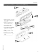
8. Check outputs (actuators) and sensors
Carry out relay test
1. Press and simultaneously for
approx. 2 seconds.
2. Select relay outputs with the or
button.
3. Press .
Relay test is activated.
Relay test is terminated.
The following relay outputs can be
selected depending on the system
equipment installed:
Burner stage 1 ON
Burner stage 1 + 2 ON
Burner modulation open
Burner modulation neutral
Burner modulation closed
Output 20 ON
Output 29 ON
Output 52 open/closed/neutral
DHW tank pump ON
DHW circulation pump ON
Heating circuit pump (M2) ON
Heating circuit pump (M3) ON
Mixing valve (M2) Open
Mixing valve (M2) Closed
Mixing valve (M3) Open
Mixing valve (M3) Closed
Central fault indicator ON
LED selector button ! illuminated.
LED selector button ! illuminated.
LED selector button ! illuminated.
LED selector button ? illuminated.
LED selector button § illuminated.
LED selector button ? illuminated.
LED selector button ? illuminated.
LED selector button § illuminated.
LED selector button § illuminated.
All LEDs extinguished.
5285 941 v.1.5
Relay test