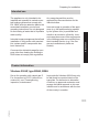
Installation and service instructions VIESMANN for contractors Vitodens 200-W Type B2HA, B2KA, 3.2 to 35 kW Gas council no. ■ System boilers: 41-819-32; 41-819-33; 41-819-34; 41-819-35 ■ Combi boilers: 47-819-28; 47-819-29; 47-819-30 For applicability, see the last page VITODENS 200-W 5772 909 GB 11/2012 Please keep safe.
Safety instructions Safety instructions Please follow these safety instructions closely to prevent accidents and material losses. Note Details identified by the word "Note" contain additional information.
Safety instructions Safety instructions (cont.) If you smell flue gas Danger The simultaneous operation of the boiler and appliances that extract air to the outside can result in life threatening poisoning due to reverse flow of the flue gas. Fit an interlock circuit or take suitable steps to ensure a sufficient supply of combustion air. Danger Flue gas can lead to life-threatening poisoning. ■ Shut down the heating system. ■ Ventilate the installation site. ■ Close all doors in the living space.
Safety instructions Safety instructions (cont.) Auxiliary components, spare and wearing parts Please note Spare and wearing parts that have not been tested together with the system can compromise its function. Installing non-authorised components and making non-approved modifications or conversions can compromise safety and may invalidate our warranty. For replacements, use only original spare parts supplied or approved by Viessmann.
Index Index Installation instructions Preparing for installation Intended use......................................................................................................... Product information.............................................................................................. Preparing for installation....................................................................................... 7 7 8 Installation sequence Fitting the boiler and making connections.............................
Index Index (cont.) Troubleshooting Fault display......................................................................................................... 110 Fault codes........................................................................................................... 112 Repairs................................................................................................................. 129 Function description Constant temperature control unit..................................................
Preparing for installation Intended use Intended usage presupposes that a fixed installation in conjunction with permissible, system-specific components has been carried out. Any usage beyond this must be approved by the manufacturer for the individual case. Incorrect usage or operation of the appliance (e.g. the appliance being opened by the system user) is prohibited and results in an exclusion of liability.
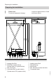
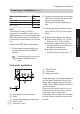
Preparing for installation Preparing for installation ! Please note To prevent equipment damage, connect all pipework free of load and torque stress. 450 100 215 50 G 360 850 1925 H 730 a A Heating flow Rp¾ B DHW Rp½ (combi boilers) Cylinder flow G¾ (system boiler) C Gas connection D Cold water Rp½ (combi boilers) Cylinder return G¾ (system boiler) 8 K E F G H K Heating return Rp¾ Filling/draining Wiring area Min.
Preparing for installation Preparing for installation (cont.) Dim. a mm 136 158 158 Note This boiler (IP rating: IP X4D) is approved for installation in wet rooms inside safety zone 1 in accordance with IEEE Wiring Regulations, providing the occurrence of hosed water can be ruled out. Observe the IEEE Wiring Regulations. 1. Fit the supplied pre-plumbing jig or mounting frame at the installation location. 2. Prepare the connections on the water side to the valves on the pre-plumbing jig or mounting frame.
Preparing for installation Preparing for installation (cont.) Remove the toggle on the cold water shut-off valve (if installed) to prevent anyone shutting it off manually. Shock arrestor 5772 909 GB If draw-off points that could cause pressure peaks (water hammer/shock) are connected to the same pipework as the boiler (such as pressure washers, washing machines or dishwashers), we would recommend the installation of a shock arrestor near the source of such pressure shocks.
Installation sequence Fitting the boiler and making connections 6. Installation 2. 4. 7. 5. 1. 2x 2x 5772 909 GB 3.
Installation sequence Fitting the boiler and making connections (cont.) Fitting the connections C Gas connection D Cold water (combi boilers) Cylinder return (system boiler) E Heating return F Filling/draining A B C D EF A Heating flow B DHW (combi boilers) Cylinder flow (system boiler) Flue gas connection Note ■ The labels "System certificate" and "Skoberne GmbH flue system" enclosed with the technical documentation may only be used in conjunction with the Viessmann flue system made by Skoberne.
Installation sequence 2. ■ The condensate pipe is connected with the discharge pipe of the safety valve. The condensate hose supplied meets the temperature requirements that are part of the CE certification. ■ We recommend the internal connection of the condensate pipe to the domestic drain, either directly or via a tundish. ■ If the condensate pipe is routed outside the building, use a pipe with 7 30 mm at least, and protect this pipe from frost. Avoid long external pipelines. 1.
Installation sequence Gas connection 3. Vent the gas line. Conversion to other gas types: Service instructions (details for converting to LPG are on page 35) A 1. Seal gas shut-off valve A into the gas supply pipe. 2. Carry out a tightness test. Note Only use suitable and approved leak detection agents (EN 14291) and devices for the tightness test. Leak detection agents with unsuitable constituents (e.g. nitrites, sulphides) can cause material damage.
Installation sequence Opening the control unit casing ! Please note Electronic assemblies can be damaged by electrostatic discharge. Before beginning work, touch earthed objects, such as heating or water pipes, to discharge static loads. 2. 2x Installation 3. 1. 5. 4x 5772 909 GB 4.
5772 909 GB 5 16 1 2 1 5 4 32 1 145 145 2 100 35 28 20 96 40 96 A 40 230V~ 230V~ N L1 L N Installation sequence Electrical connections A Jumper
Installation sequence Electrical connections (cont.) Information on connecting accessories When connecting accessories observe the separate installation instructions provided with them.
Installation sequence Electrical connections (cont.) Outside temperature sensor ! For fitting the wireless outside temperature sensor (wireless accessory): Wireless base station installation and service instructions Fitting location for outside temperature sensor ■ Not immediately below balconies or gutters ■ Never render over Outside temperature sensor connection 2-core lead, length max. 35 m with a cross-section of 1.5 mm2 ■ North or north-western wall, 2 to 2.
Installation sequence Electrical connections (cont.) Plug lH Extension EA1 B A 1 L?N DE [{A DE [{S DE [{D lH A Floating contact (when connecting, remove jumper across L and 1) Codes ■ "4b:1" in group "General"/1. ■ Effect of the function on the relevant heating circuit pump: Coding address "d7" in group "Heating circuit" (only with weather-compensated control units). ■ Effect of the function on the circulation pump for cylinder heating (if installed): Coding address "5F" in group "DHW"/ 3.
Installation sequence Electrical connections (cont.) 0-10V [{{] aBJ +- SÖ P A f-] fÖ 0 – 1 V ≙ No default set boiler water temperature 1V ≙ Set value 10 °C 10 V ≙ Set value 100 °C L?N N?L 230 V~ U 0-10 V + External blocking via switching contact Connection options: ■ Plug lH. ■ Extension EA1 (accessory, see separate installation instructions). Please note 'Live' contacts lead to short circuits or phase failure.
Installation sequence Electrical connections (cont.) Plug lH Extension EA1 A 1 L?N DE [{A DE [{S B DE [{D lH A Floating contact (when connecting, remove jumper across L and 1) A Floating contact B Extension EA1 Codes ■ Set "3A" (DE1), "3b" (DE2) or "3C" (DE3) in group "General"/1 to 3 or 4. ■ Effect of the function on the heating circuit pump: Coding address "d6" in group "Heating circuit" (only with weather-compensated control units).
Installation sequence Electrical connections (cont.) Power supply for accessories at plug lH (230 V~) Where the boiler is installed in a wet area, the power supply connection for accessories must not be made at the control unit. If the boiler is installed outside wet areas, then the power supply connection for accessories can be made directly at the control unit. This connection is switched directly with the ON/OFF switch of the control unit.
Installation sequence Electrical connections (cont.) A buffer relay must be fitted if the current flowing to the connected working parts (e.g. circulation pumps) is higher than the safety level of the relevant accessory. Accessories Internal fuse protection Extension kit for heat- 2 A ing circuit with mixer Extension AM1 4A Extension EA1 2A Solar control module, 2 A type SM1 ■ Remove the existing test wires from plug fÖ. ■ Max. fuse rating 16 A. ■ Connect the mains power supply to plug fÖ.
Installation sequence Electrical connections (cont.) Routing the connecting cables ! Please note If power cables touch hot components they will be damaged. When routing and securing cables/leads on site, ensure that the maximum permissible temperatures for these cables/leads are not exceeded.
Installation sequence Closing the control unit casing and inserting the programming unit 3. Installation 1. 2x 2. 6. 5. 4. Insert programming unit (packed separately) into the control unit support. Wall mounting base installation instructions 5772 909 GB Note The programming unit can also be inserted into a wall mounting base (accessories) near the boiler.
Installation sequence Fitting the front panel 2. 3. 1. 2x 5772 909 GB Note Fit the safety guard and ensure that the locking screws are tightened before operating.
Commissioning, inspection, maintenance Steps - commissioning, inspection and maintenance For further information regarding the individual steps, see the page indicated Commissioning steps Inspection steps Maintenance steps • • • • 1. Checking the power supply 2. Filling the heating system.............................................. 29 3. Switching on the mains voltage and ON/OFF switch 4. Language selection – only for weather-compensated control units....................................................
Commissioning, inspection, maintenance Steps - commissioning, inspection and… (cont.) Commissioning steps Inspection steps Maintenance steps • • 20. Checking and adjusting the ignition and ionisation electrodes........................................................................ 42 21. Cleaning the heating surfaces....................................... 43 • • • 23. Fitting the burner............................................................ 45 • • • • • • • • • • • 30.
Commissioning, inspection, maintenance Further details regarding the individual steps Filling the heating system Fill water ! ■ An antifreeze additive suitable for heating systems can be added to the fill water. The antifreeze manufacturer must verify its suitability. ■ Fill and top-up water with a water hardness in excess of the following values must be softened, e.g. with a small softening system for heating water.
Commissioning, inspection, maintenance Further details regarding the individual steps (cont.) Note If the control unit has not been switched on prior to filling the system, then the servomotor of the diverter valve will still be in its central position, and the system will be completely filled. 4. If the control unit had already been switched on before filling began: Switch control unit ON and activate filling function (see next chapter). 5. Close boiler drain & fill valve A.
Commissioning, inspection, maintenance Further details regarding the individual steps (cont.) Note on the automatic flue gas temperature sensor test Weather-compensated control unit As soon as the time and date have been set, the control unit automatically checks the function of the flue gas temperature sensor. The display shows: "Flue gas temp sensor test" and "Active".
Commissioning, inspection, maintenance Further details regarding the individual steps (cont.) 1. Close the shut-off valves on the heating water side. If required, remove the safety guard. 2. Push the drain hose (supplied inside the appliance) onto top valve B and connect to a drain. 3. Open valves A and B and vent at mains pressure (purge) until no sound of escaping air can be heard and no more air bubbles are visible. 4. First close valve B. 5.
Commissioning, inspection, maintenance Further details regarding the individual steps (cont.) Activating the venting function Weather-compensated control unit Service menu 1. Press OK and å simultaneously for approx. 4 s. 2. "Service functions" 3. "Venting" Venting function is enabled. 4. Ending venting function: Press OK or ä. Constant temperature control unit Service menu 1. Press OK and å simultaneously for approx. 4 s. 2. Select "5" with Ú and confirm with OK. "ON" flashes. 3.
Commissioning, inspection, maintenance Further details regarding the individual steps (cont.) Note Never twist the supply hose during assembly. Route the drain hose without any bends and with a constant fall. Designating heating circuits - only for weather-compensated control units In the delivered condition, the heating circuits are designated "Heating circuit 1", "Heating circuit 2" and "Heating circuit 3" (if installed).
Commissioning, inspection, maintenance Further details regarding the individual steps (cont.) Gas type conversion (only for operation with LPG) 1. Set adjusting screw A on the gas train to "2". 1 A 2. Turn on the ON/OFF switch 8. 2 3. Select the gas type in coding address "82": ■ Call up code 2 ■ "General" (weather-compensated control unit) or Group 1 (constant temperature control unit). ■ Select coding address "11" and set value "9". Confirm with OK. The display shows "11:0".
Commissioning, inspection, maintenance Further details regarding the individual steps (cont.) 6. Check the supply (flow) pressure. A Set value: ■ Natural gas: 20 mbar ■ LPG: 37 mbar Note ■ Use a suitable measuring device with a resolution of at least 0.1 mbar to check the supply pressure. ■ The pressure drop between the gas tap and gas valve is 0.5 mbar at full load. 1. Close the gas shut-off valve. 2.
Commissioning, inspection, maintenance Further details regarding the individual steps (cont.) Supply pressure (flow pressure) For natural gas For LPG Below 17.4 mbar Below 25 mbar 17.4 to 25 mbar Above 25 mbar Action Do not start the boiler. Notify your gas supply utility or LPG supplier. Start the boiler. Contact your gas supplier if the supply pressure is incorrect.
Commissioning, inspection, maintenance Further details regarding the individual steps (cont.) Yes Ionisation current builds Symbol A No Fault EE Check the ionisation electrode adjustment and the gas line for airlocks. Stops below the set boiler water temperature and restarts immediately Check the flue system for tightness (flue gas recirculation); check the gas flow pressure Fault E3 Ensure adequate heat transfer. Press reset button R.
Commissioning, inspection, maintenance Further details regarding the individual steps (cont.) Max. heating output setting The maximum output for heating operation can be limited. The limit is set via the modulation range. The max. adjustable heating output is limited upwards by the boiler coding card. Weather-compensated control unit Service menu 1. Press OK and å simultaneously for approx. 4 s. 2. "Service functions" 3. "Max. output" 4. "Change?" Select "Yes". A value is shown on the display (e.g. "85").
Commissioning, inspection, maintenance Further details regarding the individual steps (cont.) Burner removal G 4x E F D C B A 1. Switch OFF the power supply and the ON/OFF switch at the control unit. 2. Close the gas shut-off valve and safeguard against reopening. 5. Undo four screws G and remove the burner. ! Please note Prevent damage to the burner. Never rest the burner on the burner gauze assembly. 5772 909 GB 3.
Commissioning, inspection, maintenance Further details regarding the individual steps (cont.) Checking the burner gasket and burner gauze assembly Check burner gasket A and burner gauze assembly E for possible damage and replace if required. B F E D A 2x 2x Service C 5772 909 GB 1. Remove electrodes B. 2. Undo two retaining clips C on thermal insulation ring D and then remove thermal insulation ring D. 3. Undo two Torx screws and remove burner gauze assembly E with gasket F.
Commissioning, inspection, maintenance Further details regarding the individual steps (cont.) 6. Fit electrodes B. 4. Insert new burner gauze assembly E with new gasket F and secure. ! ! Please note Fasten screws tightly enough Please note Fasten screws tightly enough to ensure the components are not being damaged and are functioning correctly. to ensure the components are not being damaged and are functioning correctly. 5. Fit thermal insulation ring D.
Commissioning, inspection, maintenance Further details regarding the individual steps (cont.) Cleaning the heating surfaces ! Please note There should be no scratches or other damage on the heat exchanger surface that comes into contact with hot gases. This could lead to corrosion damage. Note Discolouration of the heat exchanger surface is a normal sign of usage. It has no impact on the function and service life of the heat exchanger. The use of chemical cleaning agents is not necessary.
Commissioning, inspection, maintenance Further details regarding the individual steps (cont.) A B 1. Check at the siphon that the condensate can drain freely. 2. Remove retaining clip A and siphon B. Note Never twist the supply hose during assembly. Route the drain hose without any bends and with a constant fall. 5772 909 GB 3. Clean siphon B. 4. Fill siphon B with water and fit in place. Put on retaining clip A.
Commissioning, inspection, maintenance Further details regarding the individual steps (cont.) Fitting the burner G 4x E F D C B A ! Please note Fasten screws tightly enough to ensure the components are not being damaged and are functioning correctly. Danger Escaping gas leads to a risk of explosion. Check all fittings for gas tightness. 4. Connect cables from fan motor A, gas train B, ionisation electrode C, ignition unit D and earth tab E. 5772 909 GB 2. Fit gas supply pipe F with a new gasket.
Commissioning, inspection, maintenance Further details regarding the individual steps (cont.) Checking the flow limiter (only for combi boilers) 1. Switch OFF the control unit, shut off the cold water line and drain the DHW side of the boiler. 2. Undo Allen screws A. Note Residual water may escape during dismantling. 3. Remove flow switch B and take out flow limiter C downwards. C 4. Check flow limiter C; replace if scaled or damaged, then re-insert. Refit flow switch B.
Commissioning, inspection, maintenance Further details regarding the individual steps (cont.) 3. Top up with water until the charge pressure of the cooled system is at least 1.0 bar, and is 0.1 to 0.2 bar higher than the pre-charge pressure of the expansion vessel. Permiss. operating pressure: 3 bar Checking all gas equipment for tightness at operating pressure Danger Escaping gas leads to a risk of explosion. Check all gas equipment for tightness.
Commissioning, inspection, maintenance Further details regarding the individual steps (cont.) A 4. Check the CO2 content. Should the actual value deviate from the aforementioned ranges by more than 1 %, implement steps from page 47. 5. Enter actual values into the report. 6. Set the upper heating output (see page 48). 1. Connect a flue gas analyser at flue gas port A on the boiler flue connection. 2. Open the gas shut-off valve, start the boiler and create a heat demand. 7. Check the CO2 content.
Commissioning, inspection, maintenance Further details regarding the individual steps (cont.) Matching the control unit to the heating system The control unit must be adjusted subject to the system equipment level. ■ To do this, select the relevant system scheme (see the following diagrams). ■ Set the codes in conjunction with the accessories fitted: Note Various system components are recognised automatically by the control unit and the relevant codes are adjusted automatically.
Commissioning, inspection, maintenance Further details regarding the individual steps (cont.
Commissioning, inspection, maintenance Further details regarding the individual steps (cont.
Commissioning, inspection, maintenance Further details regarding the individual steps (cont.
Commissioning, inspection, maintenance Further details regarding the individual steps (cont.
Commissioning, inspection, maintenance Further details regarding the individual steps (cont.
Commissioning, inspection, maintenance 35 Boiler water or Flow temperature in °C 1.6 1.4 80 1.2 70 1.0 60 0.8 50 0.6 40 30 3 Se 0 2 t ro 5 om 10 5 tem 20 per 15 atu 1 re in ° 0 5 C 1.8 2.0 2.8 Slope 2.6 2.4 2.2 3.0 90 3.4 3.2 Further details regarding the individual steps (cont.) 0.4 0.2 0 -5 -10 -15 -20 -25 -30 Outside temperature in °C Slope setting ranges: ■ Underfloor heating systems: 0.2 to 0.8 ■ Low temperature heating systems: 0.8 to 1.
Commissioning, inspection, maintenance Further details regarding the individual steps (cont.) D Heating circuit pump "OFF" E Heating circuit pump "ON" Changing the standard set room temperature Changing the slope and level Individually adjustable for each heating circuit.
Commissioning, inspection, maintenance Further details regarding the individual steps (cont.) Connecting the control unit to the LON system - only for weathercompensated control units The LON communication module (accessories) must be plugged in. Installation instructions LON communication module Note In the same LON system, the same subscriber number must not be allocated twice. Only one Vitotronic may be programmed as fault manager. Note The data transfer via LON can take several minutes.
Commissioning, inspection, maintenance Further details regarding the individual steps (cont.) Boiler control unit Viessmann system number, Code "98:1". LON subscriber fault monitoring, Code "9C:20". Vitotronic 200-H Viessmann system number, Code "98:1". LON subscriber fault monitoring, Code "9C:20". Carrying out a LON subscriber check The subscriber check is used to test communication with the system devices connected to the fault manager.
Commissioning, inspection, maintenance Further details regarding the individual steps (cont.) Calling up and resetting the service display The red fault indicator flashes when the limits set in coding addresses "21" and "23" have been reached. (Coding address in group "Boiler" (weathercompensated control unit) or group 2 (constant temperature control unit).
Code 1 Calling up coding level 1 Calling up coding level 1 ■ On weather-compensated control units, codes are displayed as plain text. ■ Codes that have not been assigned due to the heating system equipment level or the setting of other codes are not displayed.
Code 1 Calling up coding level 1 (cont.) Weather-compensated control unit Constant temperature control unit Resetting all codes to their delivered condition Select "Standard setting". Select "7" with Ú and confirm with OK. When " " flashes, confirm with OK. Note This also resets the codes at coding lev- Note el 2. This also resets the codes at coding level 2. "General"/group 1 Select "General" for weather-compensated control units (see page 60).
Code 1 "General"/group 1 (cont.) Value System address version 00: ...
Code 1 "General"/group 1 (cont.) Coding in the delivered condition Subscriber no. 77:1 LON subscriber number (only for weather-compensated control units) Possible change 77:2 to 77:99 LON subscriber number, adjustable from 1 to 99: 1 - 4 = Boiler 5 = Cascade 10 - 97 = Vitotronic 200-H 98 = Vitogate 99 = Vitocom Note Allocate each number only once. Lock out controls 8F:0 Operation in the standard 8F:1 menu and extended menu enabled.
Code 1 "Boiler"/group 2 Select "Boiler" for weather-compensated control units (see page 60). Select "2" for constant temperature control units (see page 60).
Code 1 "DHW"/group 3 (cont.) Coding Coding in the delivered condition Possible change Set DHW temperature reheating suppression 67:40 For solar DHW heating: 67:0 Set DHW temperature adSet DHW temperature to justable from 0 to 95 °C 40 °C. Reheating is sup- 67:95 (limited by boiler-specific pressed above the selecparameters) ted set temperature (boiler is only connected as backup if the rise in cylinder temperature is too low). Cannot be adjusted on combi boilers.
Code 1 "Solar"/group 4 (cont.) Possible change 08:10 to 08:90 Set DHW temperature adjustable from 10 to 90 °C. 0A:0 Stagnation time reduction disabled. Temperature differential adjustable from 1 to 40 K. 0A:1 to 0A:40 0F:1 to 0F:255 Flow rate adjustable from 0.1 to 25.5 l/min; 1 step ≙ 0.1 l/min. 20:1 Additional function for DHW heating. Differential temperature control 2. Differential temperature control 2 and auxiliary function. Differential temperature control 2 for central heating backup.
Code 1 "Heating circuit ..."/group 5 Select "Heating circuit ..." for weathercompensated control units (see page 60). Select "5" for constant temperature control units (see page 60).
Code 1 Coding in the delivered condition Possible change Extended economy function adjusted outside temperature A6:36 Extended economy con- A6:5 Extended economy control trol disabled (only for to enabled, i.e. the burner and weather-compensated A6:35 heating circuit pump will control units) stop and the mixer will be closed at a variable value, adjustable between 5 and 35 °C plus 1 °C. The base value is the adjusted outside temperature.
Code 1 "Heating circuit ..."/group 5 (cont.
Code 1 "Heating circuit ..."/group 5 (cont.) 5772 909 GB Coding in the delivered condition Possible change Max.
Code 1 "Heating circuit ..."/group 5 (cont.
Code 1 "Heating circuit ..."/group 5 (cont.) 5772 909 GB Coding in the delivered condition Possible change Start temperature raising F8:–5 Temperature limit for ter- F8:+10 Temperature limit adjustaminating reduced mode to ble from –5 °C, see example on F8:–60 +10 to –60 °C page 153. F8:–61 Function disabled Observe the setting of coding address "A3".
Code 2 Calling up coding level 2 Calling up coding level 2 ■ All codes are accessible in coding level 2. ■ Codes that have not been assigned due to the heating system equipment level or the setting of other codes are not displayed. ■ The heating circuit without mixer is designated "Heating circuit 1" and the heating circuits with mixer as "Heating circuit 2" or "Heating circuit 3".
Code 2 Calling up coding level 2 (cont.) Weather-compensated control unit Constant temperature control unit Resetting all codes to their delivered condition Select "Standard setting". Select "7" with Ú and confirm with OK. When " " flashes, confirm with OK. Note This also resets codes at coding level 1. Note This also resets codes at coding level 1. "General"/group 1 Select "General" for weather-compensated control units (see page 73). Select "1" for constant temperature control units (see page 73).
Code 2 "General"/group 1 (cont.
Code 2 Coding in the delivered condition Possible change 34:0 Function output A2 at ex- 34:1 Function output A2: Heattension AM1: DHW circuing circuit pump lation pump 34:2 Function output A2: Circulation pump for cylinder heating 35:0 Without extension EA1 35:1 With extension EA1 (automatic recognition) 36:0 36:1 Function output aBJ at Function output aBJ: Feed extension EA1: Fault pump message 36:2 Function output aBJ: DHW circulation pump 3A:0 Function input DE1 at ex- 3A:1 Function input DE1: Heattensi
Code 2 5772 909 GB Coding in the delivered condition Possible change 3b:0 Function input DE2 at ex- 3b:1 Function input DE2: Heattension EA1: Not asing program - changeover signed 3b:2 Function input DE2: External demand with set flow temperature. Flow temperature setting: Coding address 9b. Internal circulation pump function: Coding address 3F. 3b:3 Function input DE2: External blocking.
Code 2 "General"/group 1 (cont.) 3d:5 3E:0 DHW circulation pump runtime for brief operation: 5 min Internal circulation pump stays in control mode at signal "External blocking" 3F:0 Internal circulation pump stays in control mode at signal "External demand" 4b:0 Function input lH: Room temperature controller (Vitotrol 100). Only for constant temperature control units. 78 Possible change 3C:3 Function input DE3: External blocking.
Code 2 5772 909 GB Coding in the delivered condition Possible change 51:0 System with low loss 51:1 System with low loss headheader: er: Internal circulation pump When there is a heat dealways starts when there mand, the internal circulais a heat demand tion pump is only started if the burner is operational. Circulation pump is switched off on expiry of run-on time.
Code 2 "General"/group 1 (cont.) Coding in the delivered condition 76:0 77:1 Without LON communication module (only for weather-compensated control units) LON subscriber number (only for weather-compensated control units) Possible change 6E:51 Display correction +0.
Code 2 "General"/group 1 (cont.) Possible change 81:2 Use of the radio clock receiver (automatic recognition) 81:3 With LON communication module: The control unit receives the time 82:1 Operation with LPG (only adjustable if coding address 11:9 has been set) 82:0 Operation with natural gas 86:... 87:... 88:0 Do not adjust Do not adjust Temperature displayed in 88:1 °C (Celsius) Do not adjust. All controls active 8F:1 8F:2 8A:175 8F:0 Time constant for calculating adjusted outside temperature 21.
Code 2 "General"/group 1 (cont.) Coding in the delivered condition 98:1 Viessmann system number (in conjunction with monitoring several systems via Vitocom 300) 99:0 Do not adjust 9A:0 Do not adjust 9b:70 Set flow temperature for external demand 70 °C Possible change 98:1 System number adjustable to from 1 to 5 98:5 9C:20 9C:0 9C:5 to 9C:60 9F:8 Monitoring LON subscribers. If there is no response from a subscriber after 20 min, the values specified inside the control unit are used.
Code 2 "Boiler"/group 2 (cont.
Code 2 "Boiler"/group 2 (cont.) Coding in the delivered condition 30:1 Internal variable speed circulation pump (automatic adjustment) 31:... 38:0 Possible change 30:0 Internal circulation pump without variable speed (e.g.
Code 2 "DHW"/group 3 (cont.) 5E:0 5F:0 60:20 62:2 63:0 5772 909 GB 65:...
Code 2 "DHW"/group 3 (cont.) Coding in the delivered condition 67:40 For solar DHW heating: Set DHW temperature 40 °C. Reheating is suppressed above the selected set temperature (boiler is only connected as backup if the rise in cylinder temperature is too low). 6C:100 Set speed, internal circulation pump for DHW heating 100 % 6d:0 Draw-off function disabled (only for combi boilers) 6F:... Max.
Code 2 "Solar"/group 4 (cont.) Note The solar group is only displayed if a solar control module, type SM1, is connected. Coding 03:10 04:4 05:10 06:75 5772 909 GB 07:0 Possible change 00:2 Start temperature differento tial adjustable from 2 to 00:30 30 K. 01:1 Stop temperature differento tial adjustable from 1 to 01:29 29 K. 02:1 Solar circuit pump is speed-controlled with wave packet control. 02:2 Solar circuit pump is speed-controlled with PWM control.
Code 2 "Solar"/group 4 (cont.) 0C:1 0d:1 0E:1 0F:70 10:0 11:50 88 Delta T monitoring switched on. No flow rate captured in the solar circuit, or flow rate too low. Night circulation monitoring switched on. Unintentional flow rate is captured in the solar circuit (e.g. at night). Heat statement in conjunction with Viessmann heat transfer medium. Flow rate solar circuit at max. pump speed 7 l/min. Target temperature control switched off (see coding address "11"). Set solar DHW temperature 50 °C.
Code 2 "Solar"/group 4 (cont.) Possible change 12:0 12:1 to 12:90 20:1 20:2 20:3 20:4 20:5 20:6 20:7 5772 909 GB 20:8 20:9 No minimum limit enabled. Minimum collector temperature adjustable from 1 to 90 °C. Additional function for DHW heating. Differential temperature control 2. Differential temperature control 2 and auxiliary function. Differential temperature control 2 for central heating backup. Thermostat function. Thermostat function and auxiliary function.
Code 2 "Solar"/group 4 (cont.) Coding in the delivered condition 22:8 Start temperature differential with central heating backup (code "20:4" must be selected) 8 K. 23:4 Stop temperature differential with central heating backup (code "20:4" must be selected) 4 K. 24:40 Start temperature for thermostat function (code "20:5" or "20:6" must be selected) 40 °C. 25:50 Stop temperature for thermostat function (code "20:5" or "20:6" must be selected) 50 °C. 26:1 Priority for DHW cylinder 1 with cyclical heating.
Code 2 "Solar"/group 4 (cont.) Coding in the delivered condition Possible change After the selected cyclical heating time for the DHW cylinder without priority has expired, the rise in collector temperature is captured during the cyclical pause time. "Heating circuit ..."/group 5 Select "Heating circuit ..." for weathercompensated control units (see page 73). Select "5" for constant temperature control units (see page 73).
Code 2 "Heating circuit ..."/group 5 (cont.) Parameter Address A3:...
Code 2 "Heating circuit ..."/group 5 (cont.) Parameter address A5:... 1 2 3 4 5 6 7 to 15 With heating circuit pump logic function: Heating circuit pump "OFF" AT > RTset + 5 K AT > RTset + 4 K AT > RTset + 3 K AT > RTset + 2 K AT > RTset + 1 K AT > RTset AT > RTset – 1 K AT > RTset – 9 K 5772 909 GB A7:0 Possible change A6:5 Extended economy control to enabled, i.e.
Code 2 "Heating circuit ..."/group 5 (cont.
Code 2 "Heating circuit ..."/group 5 (cont.) Coding in the delivered condition With remote control: No room temperature-dependent heating circuit pump logic function (only for weather-compensated control units; only change the code for the heating circuit with mixer) Parameter address b5:...
Code 2 "Heating circuit ..."/group 5 (cont.
Code 2 "Heating circuit ..."/group 5 (cont.) E5:0 E6:... E7:30 E8:1 5772 909 GB E9:45 Possible change E2:0 Display correction –5 K to to E2:49 Display correction –0.1 K E2:51 Display correction +0.1 K to to E2:99 Display correction +4.
Code 2 "Heating circuit ..."/group 5 (cont.
Code 2 "Heating circuit ..."/group 5 (cont.) Possible change F9:+10 to F9:–60 FA:0 to FA:50 Fb:0 to Fb:300 Temperature limit for raising the set room temperature to the value selected for standard mode adjustable from +10 to –60 °C Temperature rise adjustable from 0 to 50 % Duration adjustable from 0 to 300 min. 5772 909 GB Service Coding in the delivered condition Observe the setting of coding address "A3".
Diagnosis and service scans Service level Weather-compensated control unit Calling up the service level Service menu: 1. Press OK and å simultaneously for approx. 4 s. 2. Select required menu. See the following diagram. Exiting the service level Service menu: 1. Select "Terminate service?". 2. Select "Yes". 3. Confirm with OK. Note The system exits the service level automatically after 30 min. Constant temperature control unit Service menu: 1. Press OK and å simultaneously for approx. 4 s.
Diagnosis and service scans Service level (cont.) Note Do not adjust menu item "Multi-boiler system". The menu item turns a weather-compensated control unit into a constant temperature control unit. Diagnosis Operating data ■ Operating data can be called up in the "i" menu. ■ For further information on operating data, see chapter "Brief scan". Service menu: 1. Press OK and å simultaneously for approx. 4 s. 2. Select required information with / .
Diagnosis and service scans Diagnosis (cont.) Weather-compensated control unit Resetting operating data Saved operating data (e.g. hours run) can be reset to "0". The value "Adjusted outside temp" is reset to the actual value. Service menu: 1. Press OK and å simultaneously for approx. 4 s. 2. "Diagnosis" 3. "Reset data" 4. Select required value (e.g. "Burner starts") or "All details". Constant temperature control unit Saved operating data (e.g. hours run) can be reset to "0". Service menu: 1.
Diagnosis and service scans 5772 909 GB For an explanation of the relevant values in the individual lines and fields, see the following table: Line (brief Field scan) 1 2 3 4 5 6 1: System schemes Software version Software version 01 to 10 Control unit Programming unit 2: 0 0 Device version Device identification ZE-ID 3: 0 0 Number of KM BUS Software version, solar subscribers control module SM1 4: Software version Type Burner control unit verBurner control unit Burner control unit sion 5: Internal detail
Diagnosis and service scans Diagnosis (cont.
Diagnosis and service scans Diagnosis (cont.) Brief scan for constant temperature control units Service menu: 1. Press OK and å simultaneously for approx. 4 s. "Ü" flashes on the display. 2. Confirm with OK. 3. Select the required scan with V/v. For example, "A" for "Max. output" (see following table): 4. Confirm selected scan with OK.
Diagnosis and service scans Diagnosis (cont.
Diagnosis and service scans Diagnosis (cont.
Diagnosis and service scans Checking outputs (actuator test) (cont.) Display Htg circ pump HC2 Mixer HC2 ON Open Mixer HC2 Close Htg circ pump HC3 Mixer HC3 ON Mixer HC3 Close Outp. int. exten.
Diagnosis and service scans Checking outputs (actuator test) (cont.
Troubleshooting Fault display Weather-compensated control unit In the event of a fault, red fault indicator A flashes. " " flashes on the display and "Fault" is shown. A R bar The fault code is displayed with OK. For an explanation of the fault code, see the following pages. For some faults, the type of fault is also displayed in plain text. Calling up acknowledged faults Select "Fault" in the standard menu. The current faults will be displayed in a list.
Troubleshooting Fault display (cont.) Constant temperature control unit In the event of a fault, red fault indicator A flashes. The two-digit fault code and (subject to the type of fault) " " or " " flash on the programming unit display. A A fault message facility, if connected, will be switched OFF. If an acknowledged fault is not remedied, the fault message will be re-displayed the following day and the fault message facility restarted. Calling up acknowledged faults R Press OK for approx. 4 s.
Troubleshooting Fault codes Displayed fault code 10 Const. Weath.- System charcomp.
Troubleshooting Fault codes (cont.) Displayed fault code 28 Const. Weath.- System charcomp. acteristics X X 30 X X 38 X X 44 X 48 X 4C X Regulates with- Lead break, out flow temflow temperaperature senture sensor sor (low loss header) Check low loss header sensor (see page 130) If no low loss header sensor is connected, set code 52:0.
Troubleshooting Fault codes (cont.) Displayed fault code 50 Const. Weath.- System charcomp.
Troubleshooting Fault codes (cont.) Const. Weath.- System charcomp. acteristics X X 99 X X 9A X X 9b X X 9C X X 9E X X 9F X X 5772 909 GB A3 X Cause Measures Check sensor / on solar control module. Control mode Check sensor aÖ on the solar control module. No solar DHW Check temperature heating sensor & on the solar control module or sensor on the Vitosolic. Control mode Lead break, Check temperature temperature sensor at connecsensor tion S3 on the Vitosolic 100.
Troubleshooting Fault codes (cont.) Displayed fault code A7 Const. Weath.- System charcomp.
Troubleshooting Fault codes (cont.) Weath.- System charcomp. acteristics Cause Measures X Control mode without remote control X Control mode without remote control Communica- Check connection error, re- tions, cable, coding mote control address "A0" in Vitotrol group "Heating heating circuit 1 circuit" and re(without mix- mote control seter) ting (see page 156). For wireless remote controls: Check connections, place remote control unit close to the boiler.
Troubleshooting Fault codes (cont.) Displayed fault code bE Const. bF Weath.- System charcomp. acteristics Cause X Control mode without remote control X Control mode Communica- Check connection error, re- tions, cable, coding mote control address "A0" in Vitotrol group "Heating heating circuit 3 circuit" and re(with mixer) mote control setting (see page 156). For wireless remote controls: Check connections, place remote control unit close to the boiler.
Troubleshooting Fault codes (cont.) Const. Weath.- System charcomp. acteristics Cause X X Control mode, max. pump speed Communication error, variable speed internal pump X Control mode, max. pump speed X Control mode, max. pump speed X Control mode, max.
Troubleshooting Displayed fault code Cd Const. Weath.- System charcomp.
Troubleshooting Fault codes (cont.) Const. Weath.- System charcomp.
Troubleshooting Fault codes (cont.) Displayed fault code E1 Const. Weath.- System charcomp. acteristics X X E3 X X E4 X X E5 X X Cause Measures Check gap between ionisation electrode and burner gauze assembly (see page 42). In open flue operation, prevent high incidence of dust in the combustion air. Press reset button R. Burner in a fault Heat transfer Ensure adequate state too low during heat transfer. calibration. Press reset button Temperature R. limiter caused shutdown.
Troubleshooting Fault codes (cont.) E8 Const. Weath.- System charcomp. acteristics X X X X Cause Burner in a fault Ionisation state current too low during calibration Burner in a fault The ionisastate tion current lies outside the permissible range Measures Check ionisation electrode: ■ Distance to burner gauze assembly (see page 42) ■ Contamination of electrode ■ Connecting lead and plug-in connections Check flue system; remedy flue gas recirculation if required. Press reset button R.
Troubleshooting Fault codes (cont.) Const. Weath.- System charcomp. acteristics X X Burner in a fault Ionisation state current outside permissible range during calibration (deviation from previous level too great) Eb X X Burner in a fault Repeated state flame loss during calibration EC X X Burner in a fault Parameter state fault during calibration 124 Cause Measures Check flue system; remedy flue gas recirculation if required.
Troubleshooting Fault codes (cont.) Displayed fault code Ed Const. Weath.- System charcomp. acteristics X X EE X X Cause Burner in a fault Internal fault state Burner in a fault Flame signal state is not present or too weak at burner start. Measures Replace control unit. Check gas supply (gas pressure and gas flow switch). Check gas train. Check ionisation electrode and connecting cable.
Troubleshooting Fault codes (cont.) Displayed fault code EF Const. Weath.- System charcomp. acteristics X X Cause Burner in a fault Flame is lost state immediately after it has formed (during the safety time). Measures Check gas supply (gas pressure and gas flow switch). Check balanced flue system for flue gas recirculation.
Troubleshooting Fault codes (cont.) Weath.- System charcomp. acteristics Cause X X Burner in a fault Flame signal state is already present at burner start. F8 X X Burner in a fault Fuel valve state closes too late.
Troubleshooting Fault codes (cont.) Displayed fault code Fd Const. Weath.- System charcomp. acteristics X X X X FF X X Burner in a fault Fault, burner state control unit Measures Check ignition electrodes and connecting cables. Check whether a strong interference (EMC) field exists near the appliance. Press reset button R. Replace control unit if fault persists. Burner blocked Boiler coding Press reset button or in a fault card or main R.
Troubleshooting Repairs Checking the outside temperature sensor X3 200 2. Test the resistance of the outside temperature sensor across terminals "X3.1" and "X3.2" on the disconnected plug and compare it with the curve. 20 10 8 6 3. Where actual values deviate severely from the curve values, disconnect the wires at the sensor and repeat the test on the sensor itself. -20 -10 0 10 20 30 Temperature in °C 4. Depending on the result, replace the lead or the outside temperature sensor.
Troubleshooting Repairs (cont.
Troubleshooting Repairs (cont.) Resistance in kΩ 20 10 8 6 4 2 1 0.8 0.6 0.4 10 30 50 70 90 110 Temperature in °C 2. Check the sensor resistance and compare it with the curve. 3. Replace the sensor in the case of severe deviation. Danger The boiler water temperature sensor is immersed in the heating water (risk of scalding). Drain the boiler on the heating water side before replacing the sensor. Sensor type: NTC 10 kΩ 5772 909 GB Service 1.
Troubleshooting Repairs (cont.) Checking the outlet temperature sensor or comfort sensor (combi boilers only) 20 Resistance in kΩ B 10 8 6 4 2 1 0.8 0.6 0.4 10 30 50 70 90 110 Temperature in °C Sensor type: NTC 10 kΩ 1. Disconnect the leads from outlet temperature sensor A or comfort sensor B. 2. Check the sensor resistance and compare it with the curve. A 3. Replace the sensor in the case of severe deviation. 5772 909 GB Note Water can leak when replacing the outlet temperature sensor.
Troubleshooting Repairs (cont.) Checking the plate heat exchanger 1. Shut off and drain the boiler on the heating water and DHW sides. 2. Release the side closures and pivot the control unit forward. A 3. Disconnect leads from comfort sensor A. 4. Remove the retaining clip and siphon B. 5. Remove thermal insulation C. 6. Undo screws D and remove plate heat exchanger E through the front.
Troubleshooting Repairs (cont.) 10. Danger Escaping gas leads to a risk of explosion. Check all gas equipment for tightness. Checking the flue gas temperature sensor The flue gas temperature sensor locks out the boiler when the permissible flue gas temperature is exceeded. Reset the interlock after the flue system has cooled down by pressing reset button R. A 1. Pull leads from flue gas temperature sensor A. 2. Check the sensor resistance and compare it with the curve. 3.
Troubleshooting Repairs (cont.) Fault "A3" during commissioning During commissioning, the control unit checks whether the flue gas temperature sensor is correctly positioned. If the flue gas temperature sensor is not positioned correctly, commissioning is cancelled and fault message A3 is displayed. 1. Check whether the flue gas temperature sensor is correctly inserted. See previous diagram. 2.
Troubleshooting Repairs (cont.) Checking the fuse A F1 1. Switch off the power. 3. Remove cover A. 2. Release the side closures and pivot the control unit down. 4. Check fuse F1 (see connection and wiring diagram).
Troubleshooting Repairs (cont.) Checking the rotational direction of the mixer motor After being switched on, the boiler implements a self-test. During this, the mixer is opened and closed again. Note The mixer motor can also be set in motion via the actuator test (see chapter "Checking outputs"). Note the rotational direction of the mixer motor during its self-test. Then set the mixer manually to "Open" again. Note The flow temperature sensor must now capture a higher temperature.
Troubleshooting Repairs (cont.) Checking flow temperature sensor Pressure drop curve Resistance in kΩ 20 10 8 6 4 2 1 0.8 0.6 0.4 10 30 50 70 90 110 Temperature in °C Sensor type: NTC 10 kΩ 1. Remove plug ? (flow temperature sensor). 2. Check the sensor resistance and compare it with the curve. Replace the sensor in the case of severe deviation. Checking the Vitotronic 200-H (accessory) 5772 909 GB The Vitotronic 200-H is connected to the control unit via the LON cable.
Function description Constant temperature control unit °C 48 s A Heating mode The selected set boiler water temperature will be maintained when a demand is being raised by the room thermostat and the heating program is set to DHW and central heating "G". The boiler water temperature will be maintained at the default frost protection temperature when there is no demand. The electronic temperature limiter inside the burner control unit limits the boiler water temperature.
Function description Constant temperature control unit (cont.) In the delivered condition, the set boiler water temperature is 20 K above the set DHW temperature (adjustable via coding address "60" in group "DHW" (weathercompensated control units) or group 3 (constant temperature control units). The burner will be switched off and the circulation pump run-on time will begin, if the actual cylinder temperature exceeds the set cylinder temperature by 2.5 K.
Function description Weather-compensated control unit (cont.) DHW heating with gas condensing combi boiler If the flow switch detects that DHW is being drawn off (> 3 l/min), the burner, circulation pump and 3-way valve are started or changed over. The burner modulates to reach the DHW outlet temperature and is limited on the boiler side by the temperature limiter.
Function description Internal extensions (accessories) Internal extension H1 ■ Heating circuit pump for heating circuit without mixer (code "53:2") ■ Circulation pump for cylinder heating (code "53:3") An external gas isolation valve can be connected to connection gD. 5772 909 GB The internal extension is integrated into the control unit casing. The following alternative functions can be connected to relay output sK.
Function description Internal extensions (accessories) (cont.) ■ Heating circuit pump for heating circuit without mixer (code "53:2") ■ Circulation pump for cylinder heating (code 53:3) An extractor fan can be switched off via connection aBJ when the burner starts. 5772 909 GB The internal extension is integrated into the control unit casing. The following alternative functions can be connected to relay output sK.
Function description External extensions (accessories) Extension AM1 Circulation pump Circulation pump Power supply fÖ A Power supply for additional accessories aVG KM BUS 5772 909 GB A1 A2 fÖ 144
Function description External extensions (accessories) (cont.) Functions Select the output functions by means of the codes on the boiler control unit.
Function description External extensions (accessories) (cont.
Function description External extensions (accessories) (cont.) The following functions can be connected alternatively: ■ External operating program changeover for each heating circuit ■ External blocking ■ External blocking with fault message input ■ External demand with minimum boiler water temperature ■ Fault message input ■ Brief operation of the DHW circulation pump External contacts must be floating. When connecting external contacts, observe the requirements of safety category II, i.e. 8.
Function description External extensions (accessories) (cont.) Analogue input 0 – 10 V Output aBJ The 0 – 10 V hook-up provides an additional set boiler water temperature: 0 – 1 V is taken as "no default for set boiler water temperature". 1V ≙ Set value 10 °C 10 V ≙ Set value 100 °C Ensure DC separation between the earth conductor and the negative pole of the on-site voltage source.
Function description Control functions (cont.
Function description Control functions (cont.) External blocking and fault message input Input DE1 Input DE2 Input DE3 The effect on the internal circulation pump is selected in coding address "3E" in group "General". Code 3A:4 3b:4 3C:4 The effect on the relevant heating circuit pump is selected in coding address "d6" in group "Heating circuit". External demand The "External demand" function is connected via extension EA1. There are 3 inputs available at extension EA1 (DE1 to DE3).
Function description Control functions (cont.) Fill program In the delivered condition, the diverter valve is set to its central position, enabling the system to be filled completely. After the control unit has been switched on, the diverter valve no longer goes into its central position. Afterwards, the diverter valve can be moved via the fill function into the central position (see "Filling the heating system").
Function description Control functions (cont.
Function description Control functions (cont.) Flow temperature °C Temperature profile 6: Code "F1:6" 60 50 40 30 20 10 1 5 10 15 20 25 30 Days 25 30 Days Flow temperature °C Temperature profile 7: Code "F1:15" 50 40 30 20 10 1 5 10 15 20 Raising the reduced room temperature Service The outside temperature limits for the start and end of temperature raising can be set in coding addresses "F8" and "F9" in the "Heating circuit" group.
Function description Control functions (cont.) Example using the settings in the delivered condition Boiler water or flow temperature in °C 90 35 80 A 70 60 50 B 40 30 3 Se 0 t ro 25 om tem 20 10 5 per 15 atu 1 re in ° 0 5 C 0 -5 -10 -15 -20 Outside temp.
Function description Control functions (cont.
Function description Allocating heating circuits to the remote control The heating circuit allocation must be configured when commissioning the Vitotrol. Heating circuit Vitotrol configuration 200A/200 RF 300A/300 RF The remote control affects the heating circuit with- H 1 HC 1 out mixer A1 The remote control affects the heating circuit with H 2 HC 2 mixer M2 The remote control affects the heating circuit with H 3 HC 3 mixer M3 Note One heating circuit can be assigned to the Vitotrol 200A/200 RF.
Function description Electronic combustion control unit (cont.) Air ratio λ– CO2/O2 content Air ratio λ O2 content (%) 1.20 1.24 1.27 1.30 1.34 1.37 1.40 1.44 1.48 3.8 4.4 4.9 5.3 5.7 6.1 6.5 6.9 7.3 CO2 content (%) for natural gas E 9.6 9.2 9.0 8.7 8.5 8.3 8.1 7.8 7.6 CO2 content (%) for natural gas LL 9.2 9.1 8.9 8.6 8.4 8.2 8.0 7.7 7.5 CO2 content (%) for LPG P 11.3 10.9 10.6 10.3 10.0 9.8 9.6 9.3 9.
Designs A1 X...
Designs Connection and wiring diagram – Internal… (cont.
Designs A1 A2 A3 160 Main PCB Power supply unit Optolink A4 A5 A6 Burner control unit Programming unit Coding card 5772 909 GB Connection and wiring diagram – External connections
Designs Connection and wiring diagram – External… (cont.) A7 A8 A9 S1 S2 X...
Parts lists Ordering individual parts Standard parts are available from your local dealer. 5772 909 GB The following information is required: ■ Serial no.
Parts lists Overview of the assemblies A C B 0003 5772 909 GB F A Type plate B Casing assembly Service D E C Heat cell assembly with burner D Control unit assembly 163
Parts lists Overview of the assemblies (cont.
Parts lists Casing (cont.
Parts lists Heat cell (cont.) Flue gas temperature sensor Heat exchanger Condensate hose O-ring 35.4 x 3.
Parts lists Heat cell (cont.
Parts lists Burner 0001 0002 0003 0004 0005 0006 0007 0012 Ionisation electrode gasket (5 pce) 0013 Ignition electrode gasket (5 pce) 0014 Blade terminal 0015 Mixture restrictor 0016 Gas nozzle ■ 19 kW: 02 yellow ■ 26 kW: 04 grey ■ 35 kW: 06 black 0017 Venturi extension 0018 Mounting plate, thermal insulation ring (2 pce) 0019 Gasket DN 65 5772 909 GB 0008 0009 0010 0011 Burner gasket (wearing part) Thermal insulation ring Cylinder burner gauze assembly Burner gauze assembly gasket Ignition electrode (
Parts lists Burner (cont.
Parts lists Hydraulics type B2HA (cont.) Clip Ø 8 (5 pce) Thermal circuit breaker Gasket set A 10 x 15 x 1.5 Temperature sensor Air vent valve G 3/8 Heat exchanger connection pipe Drain hose 10 x 1.5 x 1500 O-ring 20.6 x 2.
Parts lists Hydraulics type B2HA (cont.
Parts lists Hydraulics type B2HA (cont.
Parts lists Hydraulics type B2KA (cont.) Drain hose 10 x 1.5 x 1500 O-ring 20.6 x 2.
Parts lists Hydraulics type B2KA (cont.
Parts lists Hydraulics type B2KA (cont.
Parts lists Control unit 0001 0002 0003 0004 0005 0006 0007 0012 0013 0014 0015 0017 0018 0019 0020 0021 0022 Power cable, stepper motor Mating plug (set) Cable fixing Locking bolts, left and right Wireless outside temperature sensor Outside temperature sensor (hardwired) KM BUS connecting cable 145 Internal extension H1 Internal extension H2 Programming unit for room temperature-dependent mode 5772 909 GB 0008 0009 0010 0011 Control unit Control unit casing back panel Coding card Fuse 6.
Parts lists Control unit (cont.
Parts lists Miscellaneous (cont.
Commissioning/service reports Commissioning/service reports Static pressure Set value Commissioning Date Signature mbar kPa Supply pressure (flow pressure) mbar = for natural gas E kPa mbar = for natural gas LL kPa mbar = for LPG kPa Tick gas type Carbon dioxide content CO2 For natural gas ■ At lower heating output ■ At upper heating output For LPG ■ At lower heating output ■ At upper heating output Maintenance/ Service ≤ 57.5 ≤ 5.75 17.4-25 1.74-2.5 17.4-25 1.74-2.5 42.5-57.5 4.25-5.75 7.5-9.5 7.
Specification Specification 230 V 50 Hz 6A I IP X 4 D to EN 60529 Permissible ambient temperature ■ During operation 0 to +40 °C ■ During storage and transport –20 to +65 °C System boiler (type B2HA) Rated heating output range at TV/TR 50/30 °C kW at TV/TR 80/60 °C kW for DHW heating kW Rated heat input range kW Electronic temperature limiter setting Temperature limiter setting Backup fuse (power supply) max. 16 A 5.2 - 26 (8.8 - 26)*2 4.7 - 24.1 (8.0 24.1)*2 4.7 - 24.1 (8.0 24.1)*2 5.2 - 30 (8.
Specification Specification (cont.) Combi boiler (type B2KA) Rated heating output range at TV/TR 50/30 °C kW at TV/TR 80/60 °C kW for DHW heating kW Rated heat input kW range Power consumption In the delivered condiW tion Maximum W Connection values Relative to the max. load Natural gas E LPG P DHW flow rate at 35C rise min DHW inlet pressure min DHW flow rate Product ID 5.2 - 26 (8.8 - 26)*2 4.7 - 24.1 (8.0 - 24.1)*2 4.7 - 29.7 (8.0 - 29.7)*2 4.9 - 30.5 (8.3 - 30.5)*2 5.2 - 30 (8.8 - 30)*2 4.7 - 27.
Certificates Declaration of conformity We, Viessmann Werke GmbH&Co KG, D-35107 Allendorf, declare as sole responsible body that the product Vitodens 200-W, type B2HA and B2KA, complies with the following standards: DIN 4753 EN 483 EN 625 EN 677 EN 806 EN 55 014 EN 60 335-1 EN 60 335-2-102 EN 61 000-3-2 EN 61 000-3-3 EN 62 233 In accordance with the following Directives, this product is designated with _-0085: 92/42/EEC 2004/108/EC 2006/95/EC 2009/142/EC This product meets the requirements of the Effici
Keyword index Keyword index A Acknowledging a fault display..........110 Actuator test.....................................107 Assembly.........................................162 B Boiler water temperature sensor......130 Boosting DHW heating.....................141 Brief scans.......................................102 Burner gasket.....................................41 Burner gauze assembly.....................41 Burner removal..................................40 C Calling up fault messages.............
Keyword index Keyword index (cont.) L Language selection............................30 LON....................................................57 ■ Fault monitoring..............................58 ■ Setting subscriber numbers............57 ■ Subscriber check............................58 LON communication module..............57 M Manufacturer's certificate ................182 Mixer open/close..............................137 O Operating conditions, scanning........101 Operating data, scanning...............
5772 909 GB
5772 909 GB
5772 909 GB
7454870 7454874 Viessmann Werke GmbH&Co KG D-35107 Allendorf Telephone: +49 6452 70-0 Fax: +49 6452 70-2780 www.viessmann.com 188 7454871 7454872 Viessmann Limited Hortonwood 30, Telford Shropshire, TF1 7YP, GB Telephone: +44 1952 675000 Fax: +44 1952 675040 E-mail: info-uk@viessmann.com Subject to technical modifications. Serial No.