Commercial Vitotronic Wiring Guide Overview For use by licensed heating contractor For use with: Vitotronic 100, GC1 Vitotronic 300, GW2 Vitocontrol-S/C, VD2/CT3/RS/VB2 KK10LON Safety and Installation Requirements Please ensure that these instructions are read and understood before commencing installation. Failure to comply with instructions listed below can cause product/property damage, severe personal injury, and/or loss of life.
Table of Contents Caution, Warning Trademark Information Section 1 Control Mounting and Installation Section 2 Boiler and control overview Control mounting terminology Vitorond VD2 (490-1096MBH or 144-321KW) Vitotronic 100, GC1, Vitotronic 300, GW2 Vitorond VD2 (1255-4387MBH or 368-1285KW) Vitotronic 100, GC1 and Vitotronic 300, GW2 Vitocrossal CT3 (CT3-17 to CT3-89 models) Vitotronic 100, GC1 and Vitotronic 300, GW2 Installation of Vitocontrol-S, VD2/CT3-MW1 Boiler Control Wiring Overview Section 3 E
About these instructions Take note of all symbols and notations intended to draw attention to potential hazards or important product information. These include “WARNING”, “CAUTION” and “IMPORTANT”. See below. ! WARNING Indicates an imminently hazardous situation which, if not avoided, could result in death, serious injury or substantial product/property damage. ! CAUTION Indicates an imminently hazardous situation which, if not avoided, may result in minor injury or product/property damage.
Section 1.0 Codes The installation of this unit must be in accordance with local codes. All electrical wiring is to be done in accordance with the latest edition of CSA C22,1 Part 1 and/or local codes. In the U.S., please use the National Electrical Code ANSI/MFPA 70. The heating contractor must comply with the Standard of Controls and Safety Devices for automatically fired boilers, ANSI/ASME CSD-1 where required by the authority having jurisdiction.
Control Installation Section 2 Section 2.0 Vitorond VD2 (490-1096MBH or 144-321KW) Vitotronic 100, GC1 Vitotronic 300, GW2 Section 2.1 Vitorond VD2 (1255-4387MBH or 368-1285KW) Vitotronic 100, GC1 Vitotronic 300, GW2 Section 2.2 Vitocrossal CT3 (CT3-17 to CT3-89 models) Vitotronic 100, GC1 Vitotronic 300, GW2 Section 2.3 Installation of Vitocontrol-S, VD2/CT3/RS/VB2 Mounting Information Section 2.4 5346540 v1.
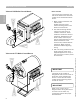
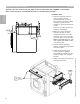
Boiler and Control Overview Section 2 Vitorond VD2 Boiler/Control/Burner Burner Conduit 3 1 Boiler control mounted on the side of boiler. Conduit from the burner harness housing points in the direction of the burner. 1 2 2 The interconnecting harness coming from the control is routed to the burner. Wires inside the conduit are wired to the burner. Depending on the burner model, there may be plug-in interconnections or hard wired connections to the terminal strip located inside of the burner.
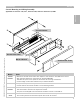
Terminology Section 2 Control Mounting and Wiring Assembly Section 2.0 Applicable for Vitotronic 100, GC1, Vitotronic 300, GW2 and Vitocontrol-S, MW1 Control Harness 5346540 v1.0 09/2006 Technical information subject to change without notice Access Hole Cover Burner Harness Name Notes Control Harness • • • • Cover Burner Harness Junction Box Cover Mounts to the side of the boiler with respect to the Vitotronic 100/300 boiler control. Wall mounting bracket for Vitocontrol-S, VD2/CT3/RS/VB2.
Installation of Boiler Controls Section 2 Vitotronic 100, GC1 and Vitotronic 300, GW2 on Vitorond VD2 boilers (490-1096MBH or 144-321KW) Refer to boiler manual for more detailed instructions on the boiler jacket assembly Installation Steps Section 2.1 1 Holes for fastening control to control harness (control mounting bracket) to side of boiler jacket. Four holes needed to properly fasten harness (bracket) to jacket with supplied screws. Drill four 1/8” holes to allow for screws to be fastened.
Installation of Boiler Controls Section 2 Vitotronic 100, GC1 and Vitotronic 300, GW2 on Vitorond VD2 boilers (490-1096MBH or 144-321KW) Refer to boiler manual for more detailed instructions on the boiler jacket assembly 6 Control is installed on two tabs at the top of the control harness (mounting plate). Control pivots down into the burner harness housing. 8 7 Control fastened down to burner harness housing with two screws.
Installation of Boiler Controls Section 2 Vitotronic 100, GC1 and Vitotronic 300, GW2 on Vitorond VD2 boilers (1255-4387MBH or 368-1285KW) Refer to boiler manual for more detailed instructions on the boiler jacket assembly Section 2.2 Installation Steps 1 Holes for fastening control to control harness (control mounting bracket) to side of boiler jacket. Four holes needed to properly fasten harness (bracket) to jacket with supplied screws. Drill four 1/8” holes to allow for screws to be fastened.
Installation of Boiler Controls Section 2 Vitotronic 100, GC1 and Vitotronic 300, GW2 on Vitorond VD2 boilers (1255-4387MBH or 368-1285KW) Refer to boiler manual for more detailed instructions on the boiler jacket assembly 6 Control is installed on two tabs at the top of the control harness (mounting plate). Control pivots down into the burner harness housing. 8 7 Control fastened down to burner harness housing with two screws.
Installation of Boiler Controls Section 2 Vitotronic 100, GC1 and Vitotronic 300, GW2 on Vitocrossal CT3 boilers (CT3-17 to CT3-89 models) Refer to boiler manual for more detailed instructions on the boiler jacket assembly Installation Steps Section 2.3 1 Side panel on Vitocrossal CT3 boiler is designed for mounting control harness without the need for drilling holes. 2 Control harness is fastened to the side of the boiler using the four supplied screws.
Installation of Vitocontrol-S, VD2/CT3-MW1 Section 2 1 Control harness (mounting bracket) is fastened to wall in similar manner as control on side of boiler. Use four screws to support bracket 273mm (10 3/4”) 500mm (19 11/16”) 2 Cover access holes with supplied blank and fasten to control harness along with junction box in step 4. Boiler Room Wall or Adjacent Boiler 3 The housing similar to that used on individual boiler control provides enclosure for DIN rail and terminal strip.
Installation of Vitocontrol-S, VD2/CT3-MW1 Section 2 Control Installation Continued 1 2 Allow control to pivot downwards and fasten control to control harness using supplied screws. 3 Install the front of the control onto the rear housing. Press downwards to ‘Click’ the front cover and rear housing together. When installed properly, the front will be allowed to pivot upwards without separating from rear of control.
Installation of Vitocontrol-S, VD2/CT3-MW1 Section 2 1 The front control housing is held in place by a support rod. The support rod is swung down from the front housing section. 2 Insert plug X20 into its respective socket. 3 Insert plug X10 into its respective socket. 4 Swing the support rod upwards by lifting rod from its locating hole. 5 Front cover is now able to swing down and close. 5 6 The control can be opened by swinging front section upwards. 7 Unclick the support rod and swing down.
Installation of Vitocontrol-S, VD2/CT3-MW1 Section 2 Control Installation Continued Section 2.4 1 1 When the control is ready to be closed, the front housing can be fastened down with three screws (supplied). Ensure there are no pinched wires between the rear portion of the control. 2 The junction box cover is used to protect and enclose the control harness DIN rail. Weave front cover edge between tabs on junction box. Pivot the cover closed and securely tighten the holding screw. 5346540 v1.
Control Wiring Installation Section 3 5346540 v1.0 09/2006 Technical information subject to change without notice General Information Installation Steps Quick Overview Boiler and control overview drawings Section 3.0 Vitotronic 100, GC1 Summary of Control Outputs Control Voltage Plug Overview Electrical Overview Section 3.1 Vitotronic 300, GW2 Summary of Control Outputs Control Voltage Plug Overview Electrical Overview 1 Electrical Overview 2 Section 3.
Control Wiring Installation Section 3 Installation Steps Quick Overview STEP 1 Review information associated with boiler and boiler control drawings STEP 2 Install boiler control onto side of boiler and plug in sensors and 120VAC plugs into control from control harness STEP 3 Supply 120VAC to control Section 3.
Control Wiring Installation Section 3 Vitorond VD2 Boiler/Control/Burner Burner Conduit 3 2 The interconnecting harness coming from the control is routed to the burner. The wires contained inside the conduit are wired to the burner. Depending on the model of burner, there may be plug-in interconnections or hard-wired connections to the terminal strip located inside of the burner. 1 2 3 Gas train wiring comes from the burner housing.
Control Overview Vitotronic 100, GC1—Electrical Section 3 Standard Control Junction Box (no modules) DIN Rail Terminal Cable Connection [21] 4 BK4 [20]A1 5 BK5 Shunt Pump/Boiler Pump [29] 6 BK6 Alarm [50] 7 BK7 [156] 8/9/10 BK8 [40] 11/G/N BK1/G/N DHW Pump Control Output Module Power Supply Incoming Power Vitotronic Plug External Safety Devices [150] 12 and 15 16 and 17 BK1 and BK3 BK 4 and BK5 Emergency Shut Off [151] 19 and 20 BK1 and BK2 20 5346540 v1.
Control Overview Vitotronic 100, GC1—Boiler/Burner Section 3 5346540 v1.0 09/2006 Technical information subject to change without notice Section 3.
Control Overview Vitotronic 100, GC1—Electrical Section 3 Overview drawing for Vitotronic 100, GC1 5346540 v1.0 09/2006 Technical information subject to change without notice Section 3.
Control Overview Vitotronic 300, GW2—Electrical Section 3 5346540 v1.0 09/2006 Technical information subject to change without notice Section 3.
Control Overview Vitotronic 300, GW2—Electrical Section 3 Plugs for control voltage and sensors for Vitotronic 300, GW2 5346540 v1.0 09/2006 Technical information subject to change without notice Section 3.
Control Overview Vitocontrol-S, CT3/VD2—Electrical Section 3 5346540 v1.0 09/2006 Technical information subject to change without notice Section 3.
Control Overview Vitocontrol-S, MW1 (CT3/VD2)—Electrical Section 3 Plugs for control voltage and sensors for Vitocontrol-S, CT3/VD2 5346540 v1.0 09/2006 Technical information subject to change without notice Section 3.
How This Section Works Section 3 5346540 v1.0 09/2006 Technical information subject to change without notice Section 3.4 Overview of control DIN rail How drawings work: Example overview drawings showing DIN rails of controls. Individual pages show plug, interconnecting wire, DIN rail terminals and output device. Pages provide breakdown of individual output and associated modules if any.
Control Overview—Power Supply Wiring Section 3 Power Control—120VAC Applicable for Vitotronic 100, GC1, Vitotronic 300, GW2 and Vitocontrol-S, CT3/VD2 1 Green [40] plug plugged into control from control installation steps. 1 2 Pre-wired interconnecting harness between [40] plug and DIN rail terminals. 3 Terminals on DIN rail inside of control junction box. Section 3.4 4 Supply voltage 120VAC terminated at terminal 11. Connection of neutral and ground as well.
Control Overview—Low Water Cut Off Wiring Section 3 Connection of Low Water Cut Off (LWCO) (Typical) Applicable for both Vitotronic 100, GC1 and 300, GW2 Installation Steps 1 White [156] plug plugged into control from control installation. Supplies 120VAC to control devices such as LWCO and valve modules. 1 2 3 Power for the LWCO is from 120VAC coming from [156] plug. The LWCO must be connected to terminal 8 or 9 or 10 inside of control junction box.
Control Overview—Control/Burner Interconnections Section 3 Connection of Boiler Control Wiring to Burner Applicable for Vitotronic 100, GC1 and Vitotronic 300, GW2 Overview 1 Control plug end [41]. Plugs into control. 2 Harness between control and burner. 1 3 Burner end of [41] plug harness. Plugs into burner. 4 Plug-in connection for [90] plug. modulation function of control. Socket for [90] plug located in control connection enclosure. 5 Cabling between control connection enclosure and burner.
Control Overview—Burner Control Wiring Section 3 Connection of Boiler Control Wiring to Burner (plug-in connection) Applicable for Vitotronic 100, GC1 Overview 1 1 Boiler control with open front access cover. 3 See Note Below 4 5346540 v1.0 09/2006 Technical information subject to change without notice 5 6 3 The [41] and [90] plug harness is fed from inside of the control into the control harness junction box. A grommet is used to hold the harness in place.
Control Overview—Burner Control Wiring Section 3 Connection of Boiler Control Wiring to Burner (hard-wired connection) Applicable for Vitotronic 100, GC1 Overview 1 1 Boiler control with open front access cover. 3 Section 3.4 See Note Below 4 5 6 3 The [41] and [90] plug harness is fed from inside of the control into the control harness junction box. A grommet is used to hold the harness in place.
Control Overview—Burner Control Wiring Section 3 Connection of Boiler Control Wiring to Burner (plug-in connection) Applicable for Vitotronic 300, GW2 Overview 1 1 Boiler control with open front access cover. 3 See Note Below 4 5346540 v1.0 09/2006 Technical information subject to change without notice 5 6 3 The [41] and [90] plug harness is fed from inside of the control into the control harness junction box. A grommet is used to hold the harness in place.
Control Overview—Burner Control Wiring Section 3 Connection of Boiler Control Wiring to Burner (hard-wired connection) Applicable for Vitotronic 300, GW2 Overview 1 1 Boiler control with open front access cover. 3 Section 3.4 See Note Below 4 5 6 3 The [41] and [90] plug harness is fed from inside of the control into the control harness junction box. A grommet is used to hold the harness in place.
Control Overview—Burner Control Wiring Section 3 Weishaupt Burner Schematic G Series Burner (typical) Refer to job specific burner schematic contained in burner information package Overview 1 Burner motor power supply connections for single phase motors. 1 -weishaupt- 2 Burner motor power supply connections for three phase motors. 2 3 Burner potentiometer used for burner positioning for BMS systems. 3 4 Modulation [90] plug connection from control or BMS.
Control Overview—Burner Control Wiring Section 3 Riello Burner Schematic (typical) Refer to job specific burner schematic contained in burner information package Overview 1 Alternate modulating control signals. Refer to burner schematic for correct applicability. 1 2 Operating control such as Vitotronic 100, GC1 or Vitotronic 300, GW2. 2 3 Modulating [90] plug output. Dry contact floating signal from control or BMS. 4 Gas valve connection. Section 3.4 5 Pilot valve.
Control Overview—Burner Power Wiring Section 3 Connection of Boiler Power Wiring to Burner Applicable for both Vitotronic 100, GC1 and 300, GW2 Soft Cable 120VAC, 1PH Supply Connection Overview 3 1 Incoming burner motor power supply 120VAC, 1PH. Ensure polarity of L/G/N is not reversed. 2 4 Soft cable 3 DIN rail mounted female socket inside boiler control junction enclosure used for wiring burner power.
Control Overview—Burner Power Wiring Section 3 Connection of Boiler Power Wiring to Burner (hard wired connection) Applicable for both Vitotronic 100, GC1 and 300, GW2 Connection Overview Flexible Conduit 240VAC, 1PH Supply 1 Incoming burner motor power supply 240VAC, 1PH. 3 2 Connect 240VAC power to terminals 21, 22 and 23 on the DIN rail inside of boiler control connection enclosure. Provide fuseable disconnect according to local codes.
Control Overview—Burner Power Wiring Section 3 Connection of Boiler Power Wiring to Burner (hardwired connection) Applicable for both Vitotronic 100, GC1 and 300, GW2 Connection Overview Flexible Conduit 208/460/575VAC, 3PH Supply 1 Incoming burner motor power supply 208/460/575VAC, 3PH. 3 2 Connect 208/460/575VAC, 3PH power to terminals 21, 22 and 23 on DIN rail inside of burner harness connection enclosure. 4 2 Flexible Conduit 1 5346540 v1.
Section 3.4 5346540 v1.
Control Overview Section 3.5 Control Output Drawings Section 3.5.1 Output [20][M2] and [M3] Heat Circuit Pump [20][M2] and [20][M3]: 120VAC Output Heat Circuit Pump [20][M2] and [20][M3]: Contactor Heat Circuit Pump [20][M2] and [20][M3]: Dry Contact Control Signal Section 3.5.2 Output [28] and [21] DHW Recirculation [28] and DHW Pump [21]: 120VAC Output DHW Recirculation [28] and DHW Pump [21]: Contactor DHW Recirculation [28] and DHW Pump [21]: Dry Contact Control Signal Section 3.5.
Control Overview—Pump Outputs Section 3 Pump Outputs—Heating Circuit Pumps [20][M2] and [20][M3]: 120VAC Output Applicable for Vitotronic 300, GW2 and Vitocontrol-S, MW1 Connection Overview 1 White [20][M2] and [20][M3] plugs are plugged into control from previous control installation steps. 1 2 Pre-wired interconnecting harness for [20][M2] and [20] [M3] plug between DIN rail terminals. 3 Terminals on DIN rail inside control junction box.
Control Overview—Pump Outputs Section 3 Pump Outputs—Heating Circuit Pumps [20][M2] and [20][M3]: Contactor Applicable for Vitotronic 300, GW2 and Vitocontrol-S, MW1 Connection Overview 1 White [20][M2] and [20][M3] plugs are plugged into control from previous control installation steps. 1 2 Pre-wired interconnecting harness for [20][M2] and [20] [M3] plug between DIN rail terminals. 2 4 Output voltage 120VAC at terminal 1 and 2 for both pump outputs. 3 5 Field supplied motor starter or contactor.
Control Overview—Pump Outputs Section 3 Pump Outputs—Heating Circuit Pumps [20][M2] and [20][M3]: Dry Contact Control Signal Applicable for Vitotronic 300, GW2 and Vitocontrol-S, MW1 Connection Overview 1 White [20][M2] and [20][M3] plugs plugged into control from control installation steps. 1 2 Pre-wired interconnecting harness for [20][M2] and [20] [M3] plug between DIN rail terminals. 3 Terminals on DIN rail inside of control junction box.
Control Overview—Pump Outputs Section 3 Pump Outputs—DHW Recirculation Pump [28] and DHW Production [21]: 120VAC Output Applicable for Vitotronic 100, GC1*, Vitotronic 300, GW2 and Vitocontrol-S, MW1 Connection Overview 1 White [28] and [21] plugs are plugged into control from previous control installation steps. 1 2 Pre-wired interconnecting harness for [28] and [21] plug between DIN rail terminals.
Control Overview—Pump Outputs Section 3 Pump Outputs—DHW Recirculation Pump [28] and DHW Production Pump [21]: Contactor Applicable for Vitotronic 100, GC1*, Vitotronic 300, GW2 and Vitocontrol-S, MW1 Connection Overview 1 White [28] and [21] plugs are plugged into control from previous control installation steps. 1 2 Pre-wired interconnecting harness for [28] and [21] plug between DIN rail terminals. 3 Terminals on DIN rail inside of control junction box.
Control Overview—Pump Outputs Section 3 Pump Outputs—DHW Recirculation [28] and DHW Pump [21]: Dry Contact Control Signal Applicable for Vitotronic 100, GC1*, Vitotronic 300, GW2 and Vitocontrol-S, MW1 Connection Overview 1 White [28] and [21] plugs are plugged into control from previous control installation steps. 1 2 Pre-wired interconnecting harness for [28] and [21] plug between DIN rail terminals.
Control Overview—Pump Outputs Section 3 Pump Outputs—Switched Output [20][A1]/[M1]: Dry Contact Control Signal Applicable for Vitotronic 100, GC1, Vitotronic 300, GW2 and Vitocontrol-S, MW1 Connection Overview 1 Refer to applicable control manual for coding information regarding this output. 1 White [20][A1]/[M1] plug is plugged into control from previous control installation steps. 2 Pre-wired interconnecting harness between [20][A1]/[M1] plug and DIN rail terminals. 2 Section 3.5.
Control Overview—Pump Outputs Section 3 Pump Outputs—Shunt Pump [29]: 120VAC Output Applicable for Vitotronic 100, GC1, Vitotronic 300, GW2 and Vitocontrol-S, MW1 Connection Overview 1 1 White [29] plug is plugged into control from previous control installation steps. 2 Pre-wired interconnecting harness between [29] plug and DIN rail terminals. 3 Terminals on DIN rail inside control junction box. 5 Connected fractional horsepower pump or circulator.
Control Overview—Pump Outputs Section 3 Pump Outputs—Shunt Pump [29]: Contactor Applicable for Vitotronic 100, GC1, Vitotronic 300, GW2 and Vitocontrol-S, MW1 Connection Overview 1 1 White [29] plug is plugged into control from previous control installation steps. 2 Pre-wired interconnecting harness between [29] plug and DIN rail terminals. 3 Terminals on DIN rail inside of control junction box. 4 Output voltage 120VAC at terminal 6 for Shunt pump. 2 Section 3.5.4 5 Connected device.
Control Overview—Pump Outputs Section 3 Pump Outputs—Shunt Pump [29]: Dry Contact Control Signal Applicable for Vitotronic 100, GC1, Vitotronic 300, GW2 and Vitocontrol-S, MW1 Connection Overview 1 1 White [29] plug is plugged into control from previous control installation steps. 2 Pre-wired interconnecting harness between [29] plug and DIN rail terminals. 4 Output voltage 120VAC at terminal 6 for Shunt/Boiler pump. Neutral and Ground terminals provided if necessary.
Control Overview—Pump Outputs Section 3 Pump Outputs—Boiler Supply Pump [29]: 120VAC Output Applicable for Vitotronic 100, GC1, Vitotronic 300, GW2 and Vitocontrol-S, MW1 Connection Overview 1 1 White [29] plug is plugged into control from previous control installation steps. 2 Pre-wired interconnecting harness between [29] plug and DIN rail terminals. 3 Terminals on DIN rail inside of control junction box. 4 Output voltage 120VAC at terminal 6 for Shunt/Boiler pump.
Control Overview—Pump Outputs Section 3 Pump Outputs—Boiler Supply Pump [29]: Contactor Applicable for Vitotronic 100, GC1, Vitotronic 300, GW2 and Vitocontrol-S, MW1 Connection Overview 1 1 White [29] plug is plugged into control from previous control installation steps. 2 Pre-wired interconnecting harness between [29] plug and DIN rail terminals. 3 Terminals on DIN rail inside of control junction box. 3 Section 3.5.4 4 Output voltage 120VAC at terminal 6 for Shunt/Boiler pump.
Control Overview—Pump Outputs Section 3 Pump Outputs—Boiler Supply Pump [29]: Dry Contact Control Signal Applicable for Vitotronic 100, GC1, Vitotronic 300, GW2 and Vitocontrol-S, MW1 Connection Overview 1 1 White [29] plug is plugged into control from previous control installation steps. 2 Pre-wired interconnecting harness between [29] plug and DIN rail terminals. 3 Terminals on DIN rail inside of control junction box. 4 Output voltage 120VAC at terminal 6 for Shunt/Boiler pump.
Control Overview—Alarm Output Section 3 Alarm Output—Compiled Alarm [50]]: 120VAC Output Applicable for Vitotronic 100, GC1, Vitotronic 300, GW2 and Vitocontrol-S, MW1 Connection Overview 1 Red [50] plug is plugged into control from previous control installation steps. 1 2 Pre-wired interconnecting harness between [50] plug and DIN rail terminals. 2 3 4 Output voltage 120VAC at terminal 7. Connection of Neutral and Ground as well can be used when powering light or buzzer..
Control Overview—Alarm Output Section 3 Alarm Output—Compiled Alarm [50]: Dry Contact Control Signal Applicable for Vitotronic 100, GC1, Vitotronic 300, GW2 and Vitocontrol-S, MW1 Connection Overview 1 Red [50] plug is plugged into control from control installation steps. 1 2 Pre-wired interconnecting harness between [50] plug and DIN rail terminals. 3 Terminals on DIN rail inside of control junction box. 2 3 4 Output voltage 120VAC at terminal 7. Section 3.5.
Control Overview—Valve Adapter Module Section 3 Valve Adapter Module—Valve Output [52][A1/M2/M3]: 24VAC or 120VAC Output Applicable for Vitotronic 100, GC1, Vitotronic 300, GW2 and Vitocontrol-S, MW1 Connection Overview 1 1 Black [52] plugs are pre-wired to modules. Plug into socket within control for specific valve output to be controlled by adaptor. 1 3 The 24VAC valve adaptor identified by two relays and transformer on PCB. Terminals on DIN rail inside control junction box.
Control Overview—Combustion Air Control Section 3 Combustion Air Device Adapter Module—Blower/Fan Single Boiler Applicable for Vitotronic 100, GC1 and Vitotronic 300, GW2 Connection Overview 1 The combustion air device adaptor module is mounted onto the DIN rail inside of the control harness connection enclosure. 2 1 2 Wire the interconnection cabling between the adaptor and control. Section 3.5.6 3 Connect the harness from the module to the [150] terminal blocks.
Control Overview—Combustion Air Control Section 3 Combustion Air Device Adaptor Module—Damper (spring close) Single Boiler Applicable for Vitotronic 100, GC1 and Vitotronic 300, GW2 Connection Overview 1 The combustion air device adaptor module is mounted onto the DIN rail inside of the control harness connection enclosure. 2 1 2 Wire the interconnection cabling between the adaptor and control. Section 3.5.6 3 Connect the harness from the module to the [150] terminal blocks.
Control Overview—Combustion Air Control Section 3 Combustion Air Device Adaptor Module—Damper (power open/close) Single Boiler Applicable for Vitotronic 100, GC1 and Vitotronic 300, GW2 Connection Overview 1 The combustion air device adaptor module is mounted onto the DIN rail inside of the control harness connection enclosure. 2 1 2 Wire the interconnection cabling between the adaptor and control. Section 3.5.6 3 Connect the harness from the module to the [150] terminal blocks.
Control Overview—Combustion Air Control Section 3 Common Combustion Air Device Interface—System Overview Applicable for Vitotronic 100, GC1 Connection Overview 1 Incoming power supply to the common combustion air device Interface. Note: Field supplied disconnect switch and circuit protection. 1 3 3 Individual boiler combustion air device adaptor. 2 4 Combustion air device: Blower Power open/spring close damper Power open/power close damper 4 5 Air proving switch connected to interface. 5346540 v1.
Control Overview—Combustion Air Control Section 3 Common Combustion Air Device Interface—System Boiler Connections Applicable for Vitotronic 100, GC1 Connection Overview 1 3 2 1 Call for heat demands from individual boiler combustion modules. Note: All demand connections are paralleled together terminated in common combustion air device interface. Section 3.5.6 2 Individual proving switch signals provide damper/blower status.
Control Overview—Combustion Air Control Section 3 Common Combustion Air Device Interface—Overview Applicable for Vitotronic 100, GC1 Connection Overview 2 1 Common combustion air device interface. 2 Incoming power supply for operation of blower or damper. Note: Power supply rated for 120VAC. 3 Boiler connection terminals from LL of combustion air device modules. Power Supply 120VAC L G N 4 Air proving switch terminals on each adaptor module. The marking NO refers to Normally Open.
Control Overview—Combustion Air Control Section 3 Common Combustion Air Device Interface—System: Blower/Damper Applicable for Vitotronic 100, GC1 Connection Overview 1 Incoming power supply to power combustion air device. Note: 120VAC supply required 1 2 Field supplied local disconnect and circuit protection. 3 Common combustion air device interface. 2 Section 3.5.6 3 4 Terminals on circuit board to terminate air proving switch from air device and terminals to power device.
Control Overview—Combustion Air Control Section 3 Common Combustion Air Device Interface—Damper Power Open/Close Applicable for Vitotronic 100, GC1 Connection Overview 1 1 Incoming power supply to power combustion air device. Note: 120VAC supply required 2 Field supplied local disconnect and circuit protection. 2 4 Terminals on circuit board to terminate air proving switch from air device and terminals to power device.
Section 3.4 5346540 v1.
External Control Connections Section 4 Overview of Considerations and Connections BMS Control Interface Considerations Control Demand Connections Overview Section 4.
External Control Connections Section 4 Control Demand Connections Overview & BMS Control Interface Considerations BMS Control Interface Considerations How to Demand Burner? How to Modulate Burner? Control Burner Demand Considerations 143 Demand Dry-contact 146 Demand Dry-contact 150 Demand Dry-contact 143/146 Demand Dry-contact 0-10VDC Demand signal Burner Modulation Considerations 0-10VDC signal direct to burner Modulation by control 90 terminal connections for BMS Section 4.
Control Overview—External Controls Connections Section 4 BMS Connections—Single/Multiple Boilers—Burner Demand Applicable for Vitotronic 100, GC1 (without communication) Burner Demand: 1st stage: dry contact to [143] plug 2nd stage: dry contact to [143] plug Connection Overview 1 Boiler control. Primary Consideration(s): Boiler maintains constant minimum boiler water temperature based on coding card with or without demand signal.
Control Overview—External Controls Connections Section 4 BMS Connections—Single/Multiple Boilers—Burner Demand Applicable for Vitotronic 100, GC1 (without communications) Burner Demand: 1st stage: dry contact to 143 plug 2nd stage: dry contact to 143 plug Connection Overview 1 Boiler control. Primary Consideration(s): Boiler will not maintain minimum boiler water temperature as long as contact at [146] plug is open. Burner will fire when control detects demand signal at [146] plug.
Control Overview—External Controls Connections Section 4 BMS Connections—Single/Multiple Boilers—Burner Demand [146] Applicable for Vitotronic 100, GC1 (without communications) Burner Disable: Dry contact to [146] plug Connection Overview Primary Consideration(s): Boiler maintains minimum boiler water temperature. Burner operation can be started with override switch. 2 Plug [146] used to interface demand signal to control via terminals 2 and 3.
Control Overview—External Controls Connections Section 4 BMS Connections—Single/Multiple Boilers—Burner Demand [150] Applicable for Vitotronic 100, GC1 (without communications) Burner Demand: Dry contact to [150] terminal block Connection Overview Primary Consideration(s): Dry contact demand part of the 120VAC burner call-for-heat circuit. Configurations: Burner demand contact wired to terminals 16 and 18 Notes: By-passes controls internal call for heat.
Control Overview—External Controls Connections Section 4 BMS Connections—Single/Multiple Boilers—Burner Disable [146] Applicable for Vitotronic 100, GC1 (without communications) Burner Disable: Dry contact to [146] plug Connection Overview Primary Consideration(s): Boiler does not maintain minimum boiler water temperature. Burner operation can be started with override switch 2 Plug [146] used to interface disable signal to control via terminals 2 and 3. Open contact disables burner. 1 Boiler control.
Control Overview—External Controls Connections Section 4 BMS Connections—Single/Multiple Boilers—Burner Disable [150] Applicable for Vitotronic 100, GC1 (without communications) Burner Disable: Dry contact to [150] terminal block Connection Overview Primary Consideration(s): Dry contact disable part of the 120VAC burner call-for-heat circuit. 1 The [150] plug is plugged into the boiler control during the installation process. This plug is yellow in colour.
Control Overview—External Controls Connections Section 4 BMS Connections—Single/Multiple Boilers—Burner/Control Disable [151] Applicable for Vitotronic 100, GC1 (without communications) Burner Disable: Dry contact to [151] terminal block. Connection Overview Configurations: Burner disable contact wired to terminals 19 and 20. Notes: Depending on how the field supplied relay is wired, it may be possible to disable the burner when the relay is powered or not powered.
Control Overview—External Controls Connections Section 4 BMS Connections—Single/Multiple Boilers—Burner Modulation [90] Applicable for Vitotronic 100, GC1 (without communications) Burner Modulation: Dry contact to [90] terminal block. Connection Overview 1 The [90] plug is plugged into the boiler control during the installation process. This plug is grey in colour. Primary Consideration(s): Dry contact for modulation is part of the 120VAC burner modulation circuit.
Control Overview—External Controls Connections Section 4 BMS Connections—External Changeover of Modulation to Staging [146] Applicable for Vitotronic 100, GC1 (without communications) External Changeover of Staged to Modulating Burner: Dry contact to [146] plug. Connection Overview Primary Consideration(s): Dual fuel equipped systems. 2 Plug [146] used to interface demand signal to control via terminals 1 and 2. Open contact removes staging burner demand. 1 Boiler control.
Control Overview—External Controls Connections Section 4 BMS Connections—Burner Demand [146] Applicable for Vitotronic 300, GW2 Burner Demand: Dry contact to 146 plug terminals 2 and 3 Connection Overview Primary Consideration(s): Burner operation can be started with override switch Adjustable high limit and electronic limit settings will limit operation of boiler/burner. 2 Plug [146] used to interface demand signal to control via terminals 2 and 3. Open contact removes burner demand.
Control Overview—External Controls Connections Section 4 BMS Connections—External Change of Heating Program/Mixing Valve Open [143] Applicable for Vitotronic 300, GW2 External Change of Heating Program OR Open Valves Demand: Dry contact to [143] plug. Connection Overview Primary Consideration(s): Only one selection allowed either External Change of Heating Program or Open Valves demand. Select which valves are affected by the change of heating program or open mixing valve demand.
Control Overview—External Controls Connections Section 4 BMS Connections—External Disable/Mixing Valve Close [143] Applicable for Vitotronic 300, GW2 External Disable/Close Mixing Valves: Dry contact to [143] plug. Connection Overview Primary Consideration(s): There is no frost protection during external disable or close mixing valves demand. No minimum boiler water temperature is maintained during the contact closure. 2 Plug [143] used to interconnect control devices with boiler control.
Control Overview—External Controls Connections Section 4 BMS Connections—Burner Demand [150] Applicable for Vitotronic 300, GW2) Burner Demand: Dry contact to 150 terminal block. Connection Overview Primary Consideration(s): Dry contact demand part of the 120VAC burner call-for-heat circuit. Configurations: Burner demand contact wired to terminals 16 and 18 Notes: By-passes controls internal call for heat. FHL and AHL still part of the burner control circuit.
Control Overview—External Controls Connections Section 4 BMS Connections—Burner Disable [150] Applicable for Vitotronic 300, GW2 Burner Disable: Dry contact to [150] terminal block Connection Overview Primary Consideration(s): Dry contact disable part of the 120VAC burner call-for-heat circuit. Configurations: Burner disable contact wired to terminals 16 and 17. Notes: Depending on how the field supplied relay is wired, it may be possible to disable the burner when the relay is powered or not powered.
Control Overview—External Controls Connections Section 4 BMS Connections—Burner/Control Disable [151] Applicable for Vitotronic 300, GW2 Burner Disable: Dry contact to 151 terminal block. Connection Overview Configurations: Burner disable contact wired to terminals 19 and 20. Notes: Depending on how the field supplied relay is wired, it may be possible to disable the burner when the relay is powered or not powered.
Control Overview—External Controls Connections Section 4 BMS Connections—External Changeover of Modulation to Staging [146] Applicable for Vitotronic 300, GW2 (without communications) External Changeover of Staged to Modulating Burner: Dry contact to [146] plug. Connection Overview Primary Consideration(s): Dual fuel equipped systems. 2 Plug [146] used to interface demand signal to control via terminals 2 and 3. Open contact removes staging burner demand. 1 Boiler control.
Control Overview—External Controls Connections Section 4 BMS Connections—External Change of Heating Program/Mixing Valve Open [143] Applicable for Vitocontrol-S, MW1 (CT3/VD2/RS/VB2) External Change of Heating Program OR Open Valves Demand: Dry contact to [143] plug. Connection Overview Primary Consideration(s): Only one selection allowed either External Change of Heating Program or Open Valves demand. Select which valves are affected by the change of heating program or open mixing valve demand.
Control Overview—External Controls Connections Section 4 BMS Connections—External Disable/Mixing Valve Close [143] Applicable for Vitocontrol-S, MW1 (CT3/VD2/RS/VB2) External Disable/Close Mixing Valves: Dry contact to [143] plug. Connection Overview Primary Consideration(s): There is no frost protection during external disable or close mixing valves demand. No minimum boiler water temperature is maintained during the contact closure. 2 Plug 143 used to interconnect control devices with boiler control.
Control Overview—External Controls Connections Section 4 BMS Connections—External Demand [146] Applicable for Vitocontrol-S, MW1 (CT3/VD2/RS/VB2) External Demand: Dry contact to [146] plug Connection Overview Primary Consideration(s): The external demand input allows a dry contact to elevate the common supply/LLH above the calculated outdoor reset value. 2 Plug [146] used to interface demand signal to control via terminals 2 and 3. Open contact removes demand. 1 Boiler control.
Control Overview—External Controls Connections Section 4 BMS Connections—Boiler Disable [143] Applicable for Vitotronic 100, GC1 in conjunction with Vitocontrol-S, MW1 (CT3/VD2) Boiler Disable: Dry contact to 143 plug to terminals 1 and 2. Connection Overview Primary Consideration(s): To be able to disable a boiler from a sequence. The boiler/shunt pump as well as the return elevation valve are tuned off/closed.
Control Overview—External Controls Connections Section 4 BMS Connections—Switch in Boiler as Last in Sequence [143] Applicable for Vitotronic 100, GC1 in conjunction with Vitocontrol-S, MW1 (CT3/VD2) Switch in boiler as last in sequence: Dry contact to [143 plug]. Connection Overview Primary Consideration(s): Changes rotation of current boiler sequence. 2 Plug [143] used to interconnect control devices with boiler control. Ensure plug [143] is plugged into the correct socket in the boiler control.
Control Overview—External Controls Connections Section 4 BMS Connections—External Changeover of Modulation to Staging [146] Applicable for Vitotronic 100, GC1 in conjunction with Vitocontrol-S, MW1 (CT3/VD2) External Changeover of Staged to Modulating Burner: Dry contact to [146] plug. Connection Overview Primary Consideration(s): Dual fuel equipped systems. 2 Plug [146] used to interface demand signal to control via terminals 1 and 2. Open contact removes staging burner demand. 1 Boiler control.
Control Overview—External Controls Connections Section 4 BMS Connections—Single/Multiple Boilers—0-10VDC 145 KM-BUS Applicable for Vitotronic 100, GC1 (without communications) 2 Connection Overview 1 Remove cover from extension input module by loosening screws on either side of front cover. They are a slotted screw head. 2 Fasten to wall or surface with screws to securely mount.
Control Overview—External Controls Connections Section 4 BMS Connections—Single/Multiple Boilers—0-10VDC 145 KM-BUS Applicable for Vitotronic 100, GC1 (without communications) Configuration: Boiler coded for 01:01 Input 0-10VDC signal wired to terminals 2 and 3 of plug [144] Boiler will maintain minimum boiler water temperature regardless of 010VDC signal. Connection Overview 1 Input Extension Module 0-10V provides signal to boiler control via 145 KM-BUS. 2 Incoming 120VAC power source.
Control Overview—External Controls Connections Section 4 BMS Connections—Single/Multiple Boilers—0-10VDC 145 KM-BUS Applicable for Vitotronic 100, GC1 (without communications) Configuration: Boiler coded for 01:03. Input 0-10VDC signal wired to terminals 2 and 3 of plug [144]. A signal of 0-1VDC, will not maintain minimum temperature. If minimum temperature necessary, contact closure 2 and 4 on [144] is necessary.
Control Overview—External Controls Connections Section 4 BMS Connections—Single Boiler—0-10VDC 145 KM-BUS Applicable for Vitotronic 300, GW2 (without communications) Connection Overview 1 1 Input Extension Module 0-10V provides signal to boiler control via 145 KM-BUS. 2 Incoming 120VAC power source. 3 Switched output. 4 Control signal 0-10VDC from BMS connected to plug [144]. 40 157 144 145 L G N 1 2 3 1 2 3 1 2 3 2 3 4 5 Plug [145] KM-BUS communication between input module to boiler control.
Control Overview—External Controls Connections Section 4 BMS Connections—Single Boiler—0-10VDC 145 KM-BUS Applicable for Vitocontrol-S, CT3/VD2, MW1 Connection Overview 1 1 Input Extension Module 0-10V provides signal to boiler control via 145 KM-BUS 2 Incoming 120VAC power source. 3 Switched output 4 Control signal 0-10VDC from BMS connected to plug [144]. 40 157 144 145 L G N 1 2 3 1 2 3 1 2 3 2 3 4 5 Plug [145] KM-BUS communication between input module to boiler control.
Section 4 5346540 v1.
Communications Section 5 Communication Interconnection Information General Information Communication card installation overview Section 5.0 Section 5.0 5346540 v1.0 09/2006 Technical information subject to change without notice Section 5.
Control Overview—External Controls Connections Section 5 LON Connections—General Installation of LON Communication Card Applicable for Vitotronic 100, GC1, Vitotronic 300, GW2 and Vitocontrol-S, CT3/VD2/RS/VB2, MW1 Connection Overview Refer to manual specific to control. Detailed information regarding coding and set up to be referenced within. 1 Open control showing location of LON card and its location within. 2 The LON card is plugged into main motherboard.
Control Overview—Extension Output Module Section 5 LON Connections—Extension Output Module (Optional) Applicable for Vitotronic 100, GC1, Vitotronic 300, GW2 Connection Overview Refer to manual specific to control. Detailed information regarding the Extension Output Module connections, coding and set-up to be referenced within. 1 1 Control showing location of LON card and its location within. 2 A CAT-5 cable is supplied with the output module.
Control Overview—External Controls Connections Section 5 LON Connections—System Overview Applicable for Vitotronic 100, GC1, and Vitocontrol-S, CT3/VD2 Connection Overview 1 Vitocontrol-S, CT3/VD2, MW1 control with communications card and end of line termination resistor. 2 Termination Resistor 2 Boiler control Vitotronic 100, GC1. Communication with up to 4 boiler controls. Interconnected with CAT-5 communication with RJ45 connector ends. Termination Resistor Section 5.
Control Overview—External Controls Connections Section 5 LON Connections—System Overview with Extension Input Module 0-10VDC Applicable for Vitotronic 100, GC1, and Vitocontrol-S, CT3/VD2 Connection Overview 1 145 1 Extension Input Module 010VDC. 2 2 Module connected to Vitocontrol-S via 145 KM-BUS connection. 3 Plug [145] connection made inside of Vitocontrol-S. 145 3 Section 5.1 5346540 v1.
Control Overview—External Controls Connections Section 5 LON Connections—System Overview with Extension Output Module Applicable for Vitotronic 100, GC1, and Vitocontrol-S, CT3/VD2 Connection Overview 1 1 Vitocontrol-S, CT3/VD2, MW1 control with communications card and end-of-line termination resistor. 2 2 Boiler control Vitotronic 100, GC1. Communication with up to 4 boiler controls. 3 Extension output module for each boiler control interconnected by CAT-5 communication cabling.
Control Overview—External Controls Connections Section 5 LON Connections—System Overview Applicable for Vitotronic 100, KK10LON, and Vitocontrol-S, CT3/VD2 Note: Shown as BUS wiring configured as free topology with RJ45 adapter. Connection Overview 1 2 3 1 3 1 6 2 3 Section 5.1 5346540 v1.0 09/2006 Technical information subject to change without notice 2 1 Plug connections in each KK10 control for terminating communication and boiler temperature sensor.
Control Overview—External Controls Connections Section 5 LON Connections—System RJ45LON Adapter Overview Applicable for Vitotronic 100, GC1, and Vitocontrol-S, RS/VB2 Connection Overview 1 1 Vitocontrol-S, RS/VB2 system control capable of communicating with up to four boiler controls Vitotronic 100, KK10LON. 2 Installation of the RJ45 LON Adaptor provides the ability to interface the two wire connection from the KK10LON controls to the Vitocontrol-S, RS/VB2.
Control Overview—LON Communications Section 5 LON Connections—System Overview BUS Topology Example Applicable for Vitotronic 100, KK10LON, and Vitocontrol-S, RS/VB2 Note: Shown as BUS wiring configured as free topology with RJ45 adapter. System Overview 1 The Vitocontrol-S unit for operation with KK10LON boiler controls. 2 2 The KK10LON boiler control is equipped with a communication board which allows it to communicate to the VitocontrolS, RS/VB2.
Control Overview—LON Communications Section 5 LON Connections—System Overview Free Topology Example Applicable for Vitotronic 100, KK10LON, and Vitocontrol-S, RS/VB2 System Overview Note: Shown as Star/Home run wiring configured as free topology with RJ45 adapter. 1 2 1 The Vitocontrol-S unit for operation with KK10LON boiler controls. 2 The KK10LON boiler control is equipped with a communication board which allows it to communicate to the VitocontrolS, RS/VB2.
Control Overview—External Controls Connections Section 5 LON Connections—System Alternative RJ45LON Adaptor Overview Applicable for Vitotronic 100, GC1, and Vitocontrol-S, CT3/VD2 Connection Overview 1 Vitotronic 100, GC1 control with communications card and end-of-line termination resistor. 1 2 Vitocontrol-S, CT3/VD2, MW1 control with communications card and end-of-line termination resistor. 3 CAT-5 Communication wire between controls, 4 Two wire cable between RJ45LON adaptors.
Section 5 5346540 v1.
Control Information Section 6 Basic Diagnostic Plug [41] Drawings Section 6.0 Vitotronic 100, GC1—Soft Cable and Flexible Conduit Plug-in Connections Hard-wire Connections Section 6.1 Vitotronic 300, GW2—Soft Cable and Flexible Conduit Plug-in Connections Hard-wire Connections Section 6.2 Section 6.0 5346540 v1.
Control Overview—Burner Control Wiring Diagnosis Section 6 Connection of Boiler Control Wiring to Burner BK Black BN Brown BU Blue GNYE Green/Yellow F6 Fixed High Limit S1 Power Switch F2 Fuse 2 TR Adjustable High Limit K1 Call for heat relay Section 6.
Control Overview—Burner Control Wiring Diagnosis Section 6 Connection of Boiler Control Wiring to Burner (plug-in connection) Applicable for Vitotronic 100, GC1 120VAC Path Overview • 120VAC on L of [40] plug. • 120VAC through S1 switch. • F2 fuse. • [151] plug jumper. • F6 Fixed high limit. • [150] plug terminal jumper across 12 and 15 (LWCO connection). • STB of 150 plug to L of [41] plug. • L of [41] plug powers flame safe guard of burner. • 120VAC returns back to control on BK3.
Control Overview—Burner Control Wiring Diagnosis Section 6 Connection of Boiler Control Wiring to Burner (hard-wired connection) Applicable for Vitotronic 100, GC1 120VAC Path Overview • 120VAC on L of [40] plug. • 120VAC through S1 switch. • F2 fuse. • [151] plug jumper. • F6 Fixed high limit. • [150] plug terminal jumper across 12 and 15 (LWCO connection). • STB of 150 plug to L of [41] plug. • L of [41] plug powers flame safe guard of burner. • 120VAC returns back to control on BK3.
Control Overview—Burner Control Wiring Section 6 Connection of Boiler Control Wiring to Burner (plug-in connection) Applicable for Vitotronic 300, GW2 120VAC Path Overview • 120VAC on L of [40] plug. • 120VAC through S1 switch. • F2 fuse. • [151] plug jumper. • F6 Fixed high limit. • [150] plug terminal jumper across 12 and 15 (LWCO connection). • STB of 150 plug to L of [41] plug. • L of [41] plug powers flame safe guard of burner. • 120VAC returns back to control on BK3. • BK3 to T1 of [41] plug.
Control Overview—Burner Control Wiring Diagnosis Section 6 Connection of Boiler Control Wiring to Burner (hard-wired connection) Applicable for Vitotronic 300, GW2 120VAC Path Overview • 120VAC on L of [40] plug. • 120VAC through S1 switch. • F2 fuse. • [151] plug jumper. • F6 Fixed high limit. • [150] plug terminal jumper across 12 and 15 (LWCO connection). • STB of 150 plug to L of [41] plug. • L of [41] plug powers flame safe guard of burner. • 120VAC returns back to control on BK3.
Vitocontrol-C System Overview Drawings Section 7 Vitocontrol-C Drawings Section 7.
5346540 v1.0 09/2006 Technical information subject to change without notice Section 7.0 118 Control voltage from control panel Plug connection within control Refer to drawings supplied with control Three wire connection Line/Ground/Neutral to be run from panel to boiler control junction box. Control Voltage: Boiler control voltage can come from custom control panel when so equipped.
Section 7.0 Burner blower motor power interconnections from control panel Single phase 120VAC Single phase 240VAC Three phase 208/460/575VAC 5346540 v1.
5346540 v1.0 09/2006 Technical information subject to change without notice Section 7.0 120 Output from boiler control to control panel. Provides signal demand for pump operation Plug connection within control Not all connections are available on all controls. Refer to control panel schematic for detailed information.
Vitocontrol-C System Overview Drawings Section 7 Section 7.0 Power connections from control panel 5346540 v1.
Section 7.0 122 5346540 v1.
Appendix Section 8 Related Information Section 8.0 Section 8.0 5346540 v1.
Appendix Section 8 Codes and Alternate Resources Applicable for Canada and USA USA The installation of this unit shall be in accordance with local codes or, in the absence of local codes use CAN/ CSA-B149.1 or CAN/CSA-B149.2 installation codes for gas burning appliances for Canada. Refer to code CSA B-139 Standard for oil burning installations. The installation of this unit shall be in accordance with local codes or, in the absence of local codes use National Fuel Gas Code ANSI Z223.
Appendix Section 8 Related Manuals Applicable for Canada and USA Line Manual Viessmann Number Version Date 1 Vitorond 200, VD2 (small) TDM 5285 661 v1.3 05/2006 2 Vitorond 200, VD2 (small) Installation Instructions 5285 663 v1.1 07/2006 3 Vitorond 200, VD2 (small) Service Instructions 5285 664 v1.2 06/2006 4 Vitorond 200, VD2 (large) TDM 5285 428 v1.3 07/2006 5 Vitorond 200, VD2 (large) Installation Instructions 5285 429 v1.
Viessmann Manufacturing Company Inc. 750 McMurray Road Waterloo, Ontario • N2V 2G5 • Canada Tel: (519) 885-6300 • Fax (519) 885-0887 www.viessmann.ca • mail@viessmann.ca 5346540 v1.0 09/2006 Technical information subject to change without notice Viessmann Manufacturing Company (U.S.) Inc. 45 Access Road Warwick, Rhode Island • 02886 • USA Tel: (401) 732-0667 • Fax (401) 732-0590 www.viessmann-us.com • mail@viessmann-us.