
Technical information
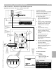
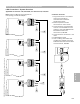
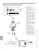


Control Overview—Extension Output Module
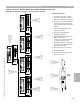
LON Connections—Extension Output Module (Optional)
Applicable for Vitotronic 100, GC1, Vitotronic 300, GW2
7
1
Refer to manual specific to control.
Detailed information regarding the
Extension Output Module
connections, coding and set-up to
be referenced within.
1 Control showing location of
LON card and its location
within.
2 A CAT-5 cable is supplied with
the output module. The RJ45 is
plugged into the control and
terminates into the output
module.
3 Output Module housing.
4 Indication LED’s within output
module. The LED status is
visible with cover on through
the label.
5 Second RJ45 socket for
termination resistor or
continuation of LON
communication to successive
boiler control.
6 The LON communication cable
from the control is plugged into
the Output Module.
7 Field-wired incoming power
supply for the output module. It
requires 120VAC for its
operation.
8 Lid of output module.
CAUTION
Static sensitive components may be
damaged by improper handling or
work within the control. Ensure all
possible measures are taken to
eliminate build-up of static electricity.
3
2
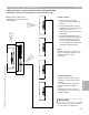
Call
Status
Burner
Alarm
LWCO
Alarm
FHL
Alarm
4
8
6
5
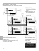
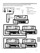
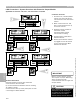
Technical Information
Power supply:
120VAC
Output Contact Rating
Maximum 30VAC/VDC
Maximum 0.5FLA
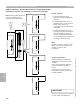
Section 5.1
Section 5
Connection Overview
5346540 v1.0 09/2006 Technical information subject to change without notice
101