
Technical information


Installation of Boiler Controls
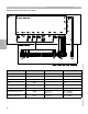
Vitotronic 100, GC1 and Vitotronic 300, GW2 on Vitorond VD2 boilers (1255-4387MBH or 368-1285KW)
Refer to boiler manual for more detailed instructions on the boiler jacket assembly
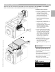
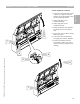
6 Control is installed on two tabs
at the top of the control
harness (mounting plate).
Control pivots down into the
burner harness housing.
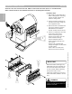
7 Control fastened down to
burner harness housing with
two screws.
8 Control limit capillaries fed
though newly created hole with
bushing in boiler jacket.
Capillaries should remain above
the boiler insulation. Insert
limits into multi-point sensor
well at back of boiler.
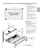
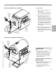
9 Cover top of boiler with jacket
panel. Slide front panel forward
to ensure panel being locked
into position. Place rear panel
on top of boiler and slide into
place. Insert two screws on
rear back lip and fasten top
panel to rear panel.
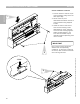
10 Pressure fit display cover onto
front of boiler by sliding left
edge into position first,
followed by pushing right side
in.
Installation Steps Continued
Section 2
Section 2.2
8
6
7
9
10
9
WARNING
!
Ensure limit capillaries are not kinked
or bent. This will adversely affect the
operation of the limit.
IMPORTANT
Insert and feed fixed high limit and
adjustable high limit capillaries, as
well as boiler temperature sensor
to rear of boiler.
Ensure limit capillaries are installed
into temperature well before
installing top panel of boiler jacket.
Ensure limits are pushed
completely into individual well.
11
5346540 v1.0 09/2006 Technical information subject to change without notice