
Technical information
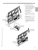


Installation of Boiler Controls
Vitotronic 100, GC1 and Vitotronic 300, GW2 on Vitocrossal CT3 boilers (CT3-17 to CT3-89 models)
Refer to boiler manual for more detailed instructions on the boiler jacket assembly
2
3
4
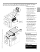
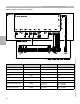
IMPORTANT
Route and insert fixed high limit,
adjustable high limit capillaries as
well as boiler temperature sensor
to rear of boiler before installing
boiler jacket and/or cover
Install limit capillaries into correct
wells and ensure pushed in all the
way.
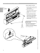
WARNING
!
Ensure limit capillaries are not kinked
or bent. This will adversely effect the
operation of the limit.
1 Side panel on Vitocrossal CT3
boiler is designed for mounting
control harness without the
need for drilling holes.
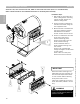
2 Control harness is fastened to
the side of the boiler using the
four supplied screws.
3 Burner harness is installed onto
the control harness. Position
behind DIN rail and fasten
screws at either end to secure.
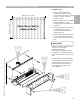
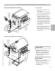
4 Control is installed on two tabs
at the top of the control
harness (mounting plate).
Control pivots down into the
burner harness housing.
Control fastened down to
burner harness housing with
two screws.
Control limit capillaries fed
though rectangular access holes
in boiler jacket.
Insert limits into multi-point
sensor well at back of boiler.
Installation Steps
Section 2
Section 2.3
1
12
5346540 v1.0 09/2006 Technical information subject to change without notice