
Technical information


1
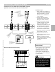
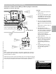
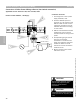
Control Overview—Low Water Cut Off Wiring
Connection of Low Water Cut Off (LWCO) (Typical)
Applicable for both Vitotronic 100, GC1 and 300, GW2
1 White [156] plug plugged into
control from control installation.
Supplies 120VAC to control
devices such as LWCO and
valve modules.
2 Yellow [150] plug used to
interrupt burner call for heat
during low water condition.
3 Power for the LWCO is from
120VAC coming from [156]
plug. The LWCO must be
connected to terminal 8 or 9 or
10 inside of control junction
box. The neutral and ground
connections are made within
one of the N and G terminals.
4 The LWCO switch is connected
to terminals 12 and 15.
5 Typical low water cut off
device which requires external
power source.
Ensure no jumpers are used
within LWCO between incoming
120VAC terminals and
switches.
2
3
4
5
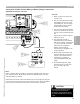
WARNING
!
When terminating a low water cut off
device to the Vitotronic 100, GC1 or
Vitotronic 300, GW2 boiler control,
the jumper found between terminals
12 and 15 must be removed and
discarded. Failure to do so will not
allow the control to be shut down a
true low water condition.
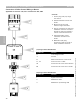
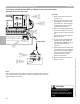
Alternate LWCO Connection Drawing
IMPORTANT
Check LWCO for correct operation
after installation and wiring
completed. Ensure the control
shuts down the burner. When
control senses tripped LWCO an
error code of C1 will be displayed
in control display.
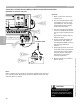
Section 3.4
Section 3
Installation Steps
5346540 v1.0 09/2006 Technical information subject to change without notice
31