
Technical information
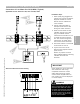
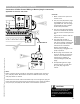


Control Overview—Control/Burner Interconnections
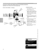
Connection of Boiler Control Wiring to Burner
Applicable for Vitotronic 100, GC1 and Vitotronic 300, GW2
1
3
2
4
5
6
1 Control plug end [41]. Plugs
into control.
2 Harness between control and
burner.
3 Burner end of [41] plug
harness. Plugs into burner.
4 Plug-in connection for [90] plug.
modulation function of control.
Socket for [90] plug located in
control connection enclosure.
5 Cabling between control
connection enclosure and
burner.
6 Modulation [90] plug.
Connection made in burner to
allow modulation of burner.
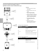
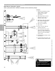
Terminal ID Function
L1 Line voltage via FHL
°
Ground
N Neutral Connection to the burner
T1, T2 Control Circuit via AHL
S3 Connection for burner fault indicator
B4 Connection for burner hour counter
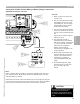
Terminal ID Function
1 Signal from burner
2 Modulation down
3 Modulation up/2nd stage ON
[90] Plug Terminal Identification
[41] Plug Terminal Identification
Section 3.4
Section 3
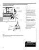
Overview
5346540 v1.0 09/2006 Technical information subject to change without notice
32