
Technical information


Control Overview—Burner Control Wiring
Connection of Boiler Control Wiring to Burner (hard-wired connection)
Applicable for Vitotronic 100, GC1
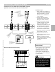
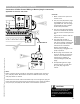
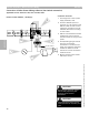
1 Boiler control with open front
access cover.
2 The [41] and [90] burner plugs
are plugged into control at far
right hand side. The two plugs
are designed for their specific
location and placement.
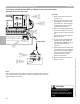
3 The [41] and [90] plug harness
is fed from inside of the control
into the control harness junction
box.
A grommet is used to hold the
harness in place.
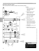
4 Control harness assemblies for
the Vitotronic 300, GW2 are
not equipped for BMS access to
the [90] plug modulation
harness.
5 Hard wired terminals are found
at the end of the control/burner
interconnection harness. Refer
to burner specific manual for
information on the proper
terminal connections.
6 Burner terminal strip located in
specific burner.
2
1
3
4
5
6
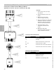
Note:
Refer to specific boiler manual for information regarding the routing of
[41] and [90] cables. Burner/boiler model will determine how the [41]
and [90] cables are routed.
See Note Below
CAUTION
!
Refer to burner manual for proper
control/burner interconnection
information. All terminations should
be double-checked before turning on
power.
Section 3.4
Section 3
Overview
5346540 v1.0 09/2006 Technical information subject to change without notice
34