
Technical information


Control Overview—Burner Control Wiring
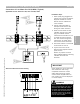
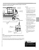
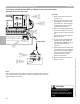
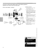
Connection of Boiler Control Wiring to Burner (plug-in connection)
Applicable for Vitotronic 300, GW2
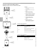
1 Boiler control with open front
access cover.
2 The [41] and [90] burner plugs
are plugged into control at far
right hand side. The two plugs
are designed for their specific
location and placement.
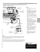
3 The [41] and [90] plug harness
is fed from inside of the control
into the control harness junction
box.
A grommet is used to hold the
harness in place.
4 The [90] plug harness is
interrupted by terminal blocks
that allow building management
or control systems to provide
remote burner modulation.
Ensure that the DIN rail
mounted plug is plugged in for
proper operation.
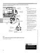
5 Burner plugs are found at end
of burner harness to allow the
control to be interfaced with
the burner by plugging in
corresponding [41] and [90]
plugs.
6 Corresponding burner plugs
found in burner to mate with
[41] and [90] plugs from
control.
2
1
3
4
5
6
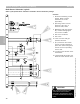
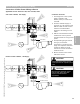
Note:
Refer to specific boiler manual for information regarding the routing of
[41] and [90] cables. Burner/boiler model will determine how the [41]
and [90] cables are routed.
Please note that some control harnesses may have a single [41] plug for
burner operation and powering of burner blower motor. Other harnesses
may have [41] and [90] for both burner and modulation operation..
See Note Below
CAUTION
!
Refer to burner manual for proper
control/burner interconnection
information. All terminations should
be double-checked before turning on
power.
Section 3.4
Section 3
Overview
5346540 v1.0 09/2006 Technical information subject to change without notice
35