
Technical information
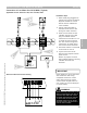


Control Overview—Burner Control Wiring
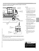
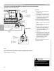
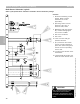
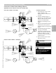
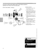
Riello Burner Schematic (typical)
Refer to job specific burner schematic contained in burner information package
1 Alternate modulating control
signals. Refer to burner
schematic for correct
applicability.
2 Operating control such as
Vitotronic 100, GC1 or
Vitotronic 300, GW2.
3 Modulating [90] plug output.
Dry contact floating signal
from control or BMS.
4 Gas valve connection.
5 Pilot valve.
6 Proof of closure and gas
pressure switches.
7 [41] connection from boiler
control provides 120VAC to
power LFL (flame safe-guard)
control as well as providing
call for heat.
8 Incoming burner blower motor
connections.
9 Field supplied disconnect and
fuses for burner blower motor.
CAUTION
!
Refer to burner manual for proper
control/burner interconnection
information. All terminations should
be double-checked before turning on
power.
Section 3.4
Section 3
1
3
7
2
4
5
6
8
9 9
Overview
5346540 v1.0 09/2006 Technical information subject to change without notice
38