
Technical information


1
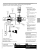
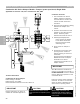
Control Overview—Combustion Air Control
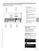
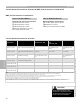
Common Combustion Air Device Interface—System Overview
Applicable for Vitotronic 100, GC1
1 Incoming power supply to the
common combustion air device
Interface.
Note: Field supplied disconnect
switch and circuit protection.
2 Common combustion air device
interface. Connections from
incoming power supply,
individual boiler adaptors and
damper/blower assembly.
3 Individual boiler combustion air
device adaptor.
4 Combustion air device:
Blower
Power open/spring close
damper
Power open/power close
damper
5 Air proving switch connected to
interface.
6 Interconnection wiring between
all applicable boilers to interface
module.
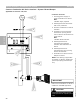
Field supplied equipment:
Power supply for damper
Local device disconnect
Device protection
Damper device with P switch
3
IMPORTANT
Ensure that combustion air device is
suitable for intended application.
CAUTION
!
Provide disconnect means and over
current protection as required by local
codes.
2
4
5
6
Section 3.5.6
Section 3
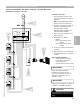
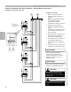
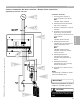
Connection Overview
IMPORTANT
A four-wire interconnection
between each boiler and the
common combustion air device
interface is required. This is a
120VAC circuit.
5346540 v1.0 09/2006 Technical information subject to change without notice
63