
Technical information


Control Overview—Combustion Air Control
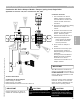
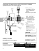
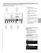
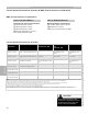
Common Combustion Air Device Interface—Overview
Applicable for Vitotronic 100, GC1
1 Common combustion air device
interface.
2 Incoming power supply for
operation of blower or damper.
Note:
Power supply rated for
120VAC.
3 Boiler connection terminals from
LL of combustion air device
modules.
4 Air proving switch terminals on
each adaptor module. The
marking NO refers to Normally
Open.
5 Connections for combustion air
device (blower or damper) and
air proving switch.
Note: 120VAC 5FLA.
IMPORTANT
Ensure that combustion air device is
suitable for intended application.
CAUTION
!
Provide disconnect means and over
current protection as required by local
codes.
NO NO L L NO NO NO NO NO NO NO NO L G N
L G N
Boiler
1-4
Boiler 4 Boiler 3
Boiler 2
Boiler 1 Proving
Switch
Power
120VAC
FRESH AIR DEVICE ADAPTORS
Power Supply
120VAC
1 2
3
4
5
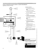
CAUTION
!
When making connections with
individual boiler interface adaptors,
ensure the power is turned off at the
boiler control.
Section 3.5.6
Section 3
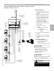
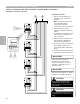
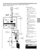
Connection Overview
IMPORTANT
A four-wire interconnection
between each boiler and the
common combustion air device
interface is required. This is a
120VAC circuit.
5346540 v1.0 09/2006 Technical information subject to change without notice
65