
Technical information


5
2
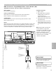
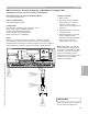
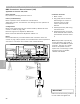
Control Overview—External Controls Connections
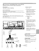
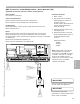
BMS Connections—Single/Multiple Boilers—Burner Demand
Applicable for Vitotronic 100, GC1 (without communication)
1
3
1 Boiler control.
2 Plug [143] used to interconnect
control devices with boiler
control. Ensure [143] plug is
plugged into the correct socket
found in the boiler control.
3 Field supplied interconnection
wire between [143] plug and
control device.
4 Field supplied relay:
24VAC
120VAC
24VDC
5 First stage demand relay (field
supplied). When coil energized,
dry contact switch is made and
control fires first stage of
burner.
6 Second stage demand relay
(field supplied). When coil is
energized, dry contact switch is
made and control drives burner
to second stage.
7 Instead of relays, it may be
possible to use simple switches
to control burner low and high
fire demands.
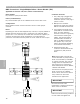
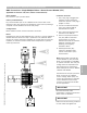
Burner Demand:
1st stage: dry contact to [143] plug
2nd stage: dry contact to [143] plug
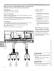
Primary Consideration(s):
Boiler maintains constant minimum boiler water temperature based on
coding card with or without demand signal.
Adjustable high limit or electronic maximum will limit operation of burner
call-for-heat.
Configurations:
1st stage demand dry contact wired to Plug [143] terminals 1 and 2.
2nd stage demand dry contact wired to Plug [143] terminals 2 and 3.
Boiler coded for 01:01.
Boiler maximum temperature limit address 06.
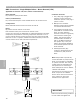
SW
143
146
143
R R
4
6
SW
OR
7
IMPORTANT
Ensure that all field wiring conforms
to local codes and regulations.
Section 4.1
Section 4
Connection Overview
IMPORTANT
Record all coding changes for future
reference.
Ensure only knowledgeable coding
changes are made.
1 2 3
5346540 v1.0 09/2006 Technical information subject to change without notice
71