
Technical information

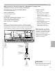

Control Overview—External Controls Connections
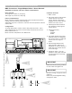
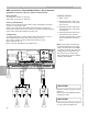
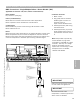
BMS Connections—Single/Multiple Boilers—Burner Modulation [90]
Applicable for Vitotronic 100, GC1 (without communications)
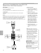
Burner Modulation:
Dry contact to [90] terminal block.
Primary Consideration(s):
Dry contact for modulation is part of the 120VAC burner modulation
circuit. Two field supplied and wired relays required.
Configurations:
Jumper between terminals [25] and [26] must be removed and discarded.
Jumper between terminals [29] and [30] must be moved across [28] and
[29].
Burner modulation downwards connect to terminals [25] and [26].
Burner modulation upwards connect to terminals [26] and [27].
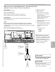
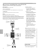
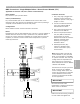
Notes:
It will not be possible to drive burner to high fire with the control mounted
override switch because of BMS modulation control.
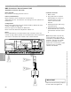
1 The [90] plug is plugged into
the boiler control during the
installation process. This plug is
grey in colour.
2 The [41] plug is plugged into
the control during the
installation process. This plug is
brown or possibly black in
colour.
3 The interconnections between
the [41] and [90] plugs are
factory wired.
4 Located on the DIN rail is a
plug/socket combination for the
burner modulation. The plug is
inserted into the socket during
installation and can be
unplugged to disable
modulation.
5 Field supplied and wired
modulation down relay.
6 Field supplied and wired
modulation up relay.
Note: Relays used to provide dry
contact modulation to [90]
terminal block are controlled by
local BMS or system controller.
The relay coil voltage must be
compatible with the system that is
controlling it. Some examples of
this are: 24VAC, 120VAC,
24VDC.
Connections to the [90] terminal
block are part of the 120VAC
control voltage circuit.
IMPORTANT
Ensure that all field wiring conforms
to local codes and regulations.
3
4
1
2
R R
3
5 6
Section 4.1
Section 4
Connection Overview
5346540 v1.0 09/2006 Technical information subject to change without notice
78