
Technical information


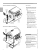
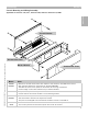


Installation of Boiler Controls
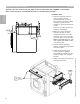
Vitotronic 100, GC1 and Vitotronic 300, GW2 on Vitorond VD2 boilers (490-1096MBH or 144-321KW)
Refer to boiler manual for more detailed instructions on the boiler jacket assembly
Measurements shown in Imperial and Metric units
1 Holes for fastening control to
control harness (control
mounting bracket) to side of
boiler jacket. Four holes needed
to properly fasten harness
(bracket) to jacket with supplied
screws.
Drill four 1/8” holes to allow for
screws to be fastened.
2 Make 7/8” hole to feed limit
capillaries as well as boiler
temperature sensor into boiler
jacketing. The limits and sensor
are to be drawn to rear of boiler.
Note: Grommet/Bushing for 7/8”
hole supplied with boiler control
in accessory bag.
3 Control harness (mounting
bracket) is held onto boiler jacket
with four screws.
4 Install burner harness onto
control harness by guiding
behind DIN rail. Fasten with two
screws at either end of burner
harness.
5 Install cover with two screws at
front of boiler jacket.
Installation Steps
Section 2
Section 2.1
5
1
2
3
4
8
5346540 v1.0 09/2006 Technical information subject to change without notice