
Technical information

2
Control Overview—External Controls Connections
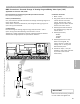
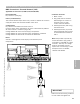
BMS Connections—Burner Demand [150]
Applicable for Vitotronic 300, GW2)
Burner Demand:
Dry contact to 150 terminal block.
Primary Consideration(s):
Dry contact demand part of the 120VAC burner call-for-heat circuit.
Configurations:
Burner demand contact wired to terminals 16 and 18
Notes:
By-passes controls internal call for heat.
FHL and AHL still part of the burner control circuit.
Control can call burner on depending on coding/configuration (minimum
temperature).
Control override switch remains functional (low fire) when switched.
Removal of 16 to 17 jumper, override not functional and inactive.
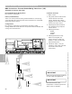
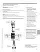
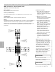
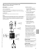
1 The [150] plug is plugged into
the boiler control during the
installation process. This plug is
yellow in colour.
2 Multiple wire conductor
between [150] plug and the DIN
rail mounted terminal block.
3 Two jumpers are found on the
[150] DIN rail mounted terminal
block. A jumper between
terminals 12 and 15 is generally
removed when installing the
LWCO. The second jumper is
found between terminals 16
and 17 for BMS connections.
This jumper may or may not
need to be removed depending
on the desired control
functionality.
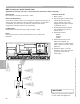
4 Field supplied relay (dry
contact) to demand burner ON
connected to [150] terminal
block.
Note: Relays used to provide dry
contact demands to [150] terminal
block are controlled by local BMS
or system controller. The relay coil
voltage must be compatible with
the system that is controlling it.
Some examples of this are 24VAC,
120VAC and 24VDC.
Connections to the [150] terminal
block are part of the 120VAC
burner call-for-heat circuit. Ensure
relay contacts or switch are
suitable for this application.
1
3
4
R
IMPORTANT
Ensure that all field wiring conforms
to local codes and regulations.
Section 4.2
Section 4
Connection Overview
5346540 v1.0 09/2006 Technical information subject to change without notice
83