
Technical information


Control Overview—External Controls Connections
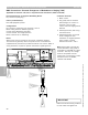
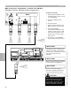
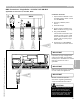
BMS Connections—Single/Multiple Boilers—0-10VDC 145 KM-BUS
Applicable for Vitotronic 100, GC1 (without communications)
1 Remove cover from extension
input module by loosening
screws on either side of front
cover. They are a slotted screw
head.
2 Fasten to wall or surface with
screws to securely mount.
3 All connections to the extension
input module are made using
the supplied plugs and installing
the plugs into the respective
socket on the circuit board.
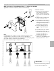
4 Incoming 120VAC power to
module via grounded plug-in
cable.
5 Switched output from module.
6 Input signal 0-10VDC onto
terminals 2 and 3 of [144] plug.
Terminal 2 of plug 144 is —
Terminal 3 of plug 144 is +
7 Communication to boiler
controls via [145] KM-BUS onto
plug [145] terminals 1 and 2.
IMPORTANT
Ensure that all field wiring conforms
to local codes and regulations.
1
2
3
4
5 6 7
Section 4.4
Section 4
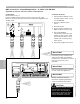
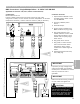
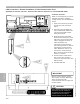
Connection Overview
Note:
Coding address 9d is coded to 01 when module connected to control.
Coding address 01 must be set to either 01 or 03 depending on
application. Minimum temperature is maintained when input signal greater
than 1VDC. Refer to manual for proper addressing.
DIP switch selectable range of temperatures, refer to manual
5346540 v1.0 09/2006 Technical information subject to change without notice
93