
Technical information


Control Overview—External Controls Connections
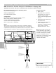
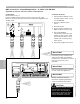
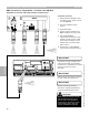
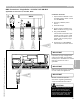
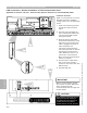
BMS Connections—Single/Multiple Boilers—0-10VDC 145 KM-BUS
Applicable for Vitotronic 100, GC1 (without communications)
1 Input Extension Module 0-10V
provides signal to boiler control
via 145 KM-BUS.
2 Incoming 120VAC power
source.
3 Switched output.
4 Control signal 0-10VDC from
BMS connected to plug [144].
5 Plug [145] KM-BUS
communication between input
module to boiler control. Field
wired and terminated in input
module and into [145] plug in
boiler control.
6 Plug [145] plugged into control.
IMPORTANT
Ensure that all field wiring conforms
to local codes and regulations.
40 157 144 145
1 2 3 1 2 3 1 2 3 L G N
145
1 2 3
145
2 3 4
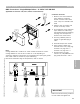
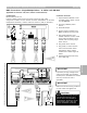
Configuration:
Boiler coded for 01:01
Input 0-10VDC signal wired to terminals 2 and 3 of plug [144]
Boiler will maintain minimum boiler water temperature regardless of 0-
10VDC signal.
6
5
1
IMPORTANT
Review manuals for specific
information regarding addressing,
values and detailed information.
CAUTION
!
When routing and running wiring for
communication between control
devices, there is the possibility of
electromagnetic interference. Avoid
running wires beside or near high
voltage 120/240VAC conductors.
IMPORTANT
If proximity to high voltage wires
cannot be avoided, use stranded,
twisted pair or shielded wire. Ensure
that only one end of wire is
grounded.
Section 4.4
Section 4
Connection Overview
5346540 v1.0 09/2006 Technical information subject to change without notice
94