
Technical data


19
5354 787 - 01
Vitorond 200, VD2A Technical Data
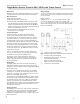
Single-Boiler System: Vitorond 200, VD2A with Therm-Control
Boiler Control
DHW heating
The DHW is heated up when the actual temperature
falls below the DHW temperature selected for the tank
temperature sensor, subject to tank heating being enabled
by the time switch.
The boiler water temperature is raised to the set DHW
temperature +20 K (36º F) and the tank primary pump
is started, if the boiler water temperature is 7 K (12.6º F)
above the actual DHW temperature.
The heating circuit pumps M2 and M3 are closed, subject
to absolute priority being enabled, if the heating circuits
are regulated via the Vitotronic. Subject to modulating
priority, the heating circuit pumps M2 and M3 remain
switched ON and the mixing valves M2 and M3 are closed
far enough for the set boiler water temperature for tank
heating to be achieved.
Heating operation
Depending on the control unit used, the flow temperature
of heating circuits can be operated in modulating mode,
subject to the outside temperature. The boiler water
temperature is regulated 8 K (14.4º F) higher than the set
flow temperature.
Applications
Heating system with manifold installed close to the boiler.
The boiler water flow rate must be able to be reduced.
Main components
Single boiler system with:
H Vitorond 200, VD2A, 125 to 270.
H Vitotronic 300, GW2/GW2B model or Vitotronic 100,
GC1/GC1B model with Vitocontrol panel and integral
weather-compensated Vitotronic 200-H, HK1M/HK1B
model or Vitotronic 100, GC1/GC1B model and external
weather-compensated control unit.
H Therm-Control for operating boilers without low
temperature return package.
Function description
The Therm-Control will affect the heating control
unit(s) or the heating circuit pump(s), if the factory-
set temperatures are not reached at the Therm-Control
temperature sensor. In the start-up phase (e.g. during
commissioning or after a night or weekend shutdown),
the boiler water flow rate must be reduced by at least 50%.
The boiler is protected to an optimum level when using
the Vitotronic 300, GW2/GW2B model or if the heating
circuits are regulated via a Vitotronic 200-H connected
to the boiler control unit. No additional on-site protective
measures are required.
When it is impossible to reduce the boiler water flow
rate, e.g. in older systems, we recommend contacting
Viessmann for other possible piping layouts.
No minimum return water temperature needs to be
maintained. Shunt pumps and/or boiler circuit pumps/
costly mixing valves are not required for elevating the
return temperature.
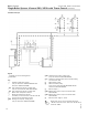
Legend
A Contactor relay, field supplied
sÖA1 Closing mixing valves (Vitotronic 100, GC1/GC1B)
A Contactor relay, field supplied
B Downstream heating circuit control unit
Switching contact closed:
signal for close mixing valve(s)
C Power connection 120 VAC 60 Hz
D Junction box, field supplied
The Therm-Control wiring in heating systems with heating
circuit control units, is not connected to the boiler control
unit via the LON.
Required coding:
Change “4C” to “2” - use the plug-in connector sÖA1
to close the downstream mixing valve. Change “0D”
to “1” - the Therm-Control acts on the mixing valve of the
downstream heating circuits (for Vitotronic 200 and 300,
factory set condition).
Closed Closed Closed
1 2 . . . n
Wiring Diagram