Installation Instructions for use by heating contractor Vitocell 100 CVA-Series Enameled indirect-fired domestic hot water storage tank 42 USG to 120 USG (160 L to 450 L) capacity VITOCELL 100-V r CAUTION The heat transfer medium must be water or other non-toxic fluid having a toxicity rating or class of 1, as listed in clinical toxicology of commercial products, 5th edition. This tank version is not suitable for steam heating applications.
Introduction Vitocell 100-V Installation Instructions Safety, Installation and Warranty Requirements Please ensure that these instructions are read and understood before commencing installation. Failure to comply with the instructions listed below and details printed in this manual can cause product/property damage, severe personal injury, and/or loss of life. Ensure all requirements below are understood and fulfilled (including detailed information found in manual subsections).
Vitocell 100-V Installation Instructions Contents Page Introduction Safety, Installation and Warranty Requirements..............2 Licensed professional heating contractor.....................2 Product documentation.............................................2 Advice to owner......................................................2 Warranty................................................................2 Safety Important Regulatory and Installation Requirements........4 Codes.............................
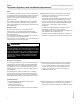
Safety Vitocell 100-V Installation Instructions Important Regulatory and Installation Requirements Codes The installation of indirect-fired hot water storage tanks in boilers and solar system application might be governed by individual local rules and regulations for this type of product, which must be observed. Always use latest editions of codes.
Vitocell 100-V Installation Instructions General Information About These Instructions Take note of all symbols and notations intended to draw attention to potential hazards or important product information. These include “WARNING”, “CAUTION”, and “IMPORTANT”. See below. WARNING Indicates an imminently hazardous situation which, if not avoided, could result in substantial product/property damage, serious injury or loss of life.
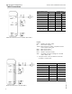
Set-up and Connections Vitocell 100-V Installation Instructions Tank Connections Supplied adaptor sizes Vitocell 100-V Part Size 42/53 USG (160/200 L) 79 USG (300 L) B Brass cap c in. 1 -- A Brass adaptor c in. 2 -- C Brass tee c in. 1 -- F Brass adaptor 1 in. + gasket 2 2 B Brass cap 1 in. -- 1 A Brass adaptor 1 in. -- 2 C Brass tee 1 in. -- 1 E Temperature and pressure relief valve c in.
Set-up and Connections Vitocell 100-V Installation Instructions Tank Set-up - For narrow passageways, remove upper and lower portion of crating and carry DHW tank to its installation location by means of crating boards mounted on the tank. - Position tank carefully and remove wood crating. - Locate tank(s) on flooring or foundation capable of supporting the weight of the tank(s) filled with water. - The tank does not require a special foundation and can be placed directly on the floor.
Set-up and Connections Vitocell 100-V Installation Instructions 42 to 79 USG (160 to 300 Liter) Tank Installation Thermal insulation and thermometer installation All required components are included in the insulation jacket carton. Note: the 42 to 79 USG (160 and 300 L) tank comes with the insulation jacket installed. IMPORTANT Do not extend the leveling bolts beyond an overall length of 1½ in. (35 mm). 2.
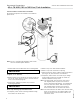
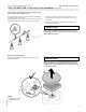
Set-up and Connections Vitocell 100-V Installation Instructions 42 to 79 USG (160 to 300 Liter) Tank Installation (continued) Temperature sensor installation for solar operation using 42 to 79 USG (160 to 300 L) tanks The temperature sensor for solar operation is included in the solar control unit package. The brass elbow with sensor well is available as an option and must be used when solar connection is required. 1.
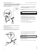
Set-up and Connections Vitocell 100-V Installation Instructions 120 USG (450 Liter) Tank Installation Temperature sensor installation (when using a Vitotronic 200 / 300 or Vitodens 200) 1. Mount sensor on the outside of the sensor spring-clip (not in the center groove) so that it is flush with the front of the sensor spring-clip. 2. Snap sensor cabling into plastic clip of sensor mounting equipment. CAUTION Never wrap sensor with any type of tape or insulation. 3.
Set-up and Connections Vitocell 100-V Installation Instructions 120 USG (450 Liter) Tank Installation (continued) Levelling and bottom thermal insulation All necessary parts for enclosure assembly are packaged in a separate carton. 1. Fit the thermal insulation blanket below the tank prior to the installation of the tank itself. 2. Position and level the DHW tank with its leveling bolts. CAUTION 5608 487 v1.2 The thermal insulation must not come in contact with open flames.
Set-up and Connections 120 USG (450 Liter) Tank Installation Vitocell 100-V Installation Instructions (continued) Fitting the thermal insulation jacket Note: - insulation remnants must not enter the tank through the tank connections. - 2 people are recommended to complete this work. 1. Fit both halves of the insulation jacket close to the tank. Orient the jacket so the profile cutouts match the tank fittings. 2.
Set-up and Connections Vitocell 100-V Installation Instructions 120 USG (450 Liter) Tank Installation (continued) Fitting the thermometer and thermometer sensor (if supplied) and covers 1. Smooth out the insulation jacket by tapping the jacket evenly against the tank. 2. Route thermometer capillary tube through the front cover hole and insulation jacket, then snap the thermometer in place. 3. Insert the thermometer probe under the clip. 5608 487 v1.2 4.
Set-up and Connections Vitocell 100-V Installation Instructions Aquastat Installation (when using a Vitotronic 100) Where a Vitotronic 100 and a Viessmann Power/Pump Control Module (accessory) are utilized to control DHW production, follow these aquastat mounting instructions: Probe style aquastat 1. Insert the extended capillary of the aquastat (supplied with Viessmann Power/Pump Control Module, not illustrated) fully and completely into sensor well. Mount aquastat inconspicuously on tank paneling.
Set-up and Connections Vitocell 100-V Installation Instructions Boiler Water Connections (heat exchanger connection) Recommended piping for solar application with an additional tank Legend A B C D E F G Solar collector High limit safety cut-out Filling valve Solar-Divicon Vitocell 100-V Individual DHW tank heating system Anti-scald tempering valve WARNING Due to the potentially high DHW temperatures generated by the solar heating system, the domestic hot water temperature must be limited to a maximum
Set-up and Connections Vitocell 100-V Installation Instructions Domestic Water Connections Note: - Connect all pipe work with detachable fittings. Seal connections that are not required with red brass caps. Equip the DHW circulation pipe with circulation pump, check valve and time switch. Gravity operation is only feasible to a limited degree. Always install DHW group of tanks with connected DHW circulation. 1. Pipe together boiler and tank as illustrated.
Set-up and Connections Vitocell 100-V Installation Instructions Domestic Water Connections (continued) Always ensure the use of type approved devices.
Set-up and Connections Vitocell 100-V Installation Instructions Recirculation Connections Pipe domestic hot water supply piping with tank as illustrated. Connections must be accessible for service (use factory supplied adaptors). Install recirculation pump, flow check valve and recirculation timer (for shut-down during off-hours where feasible) on the recirculation piping side.
Set-up and Connections Vitocell 100-V Installation Instructions Multiple Tank Set-up [only for 79 and 120 USG (300 and 450 L) capacities] Two tanks, each with 79 USG (300 L) content, or up to four tanks, each with 120 USG (450 L) content, may be installed side-by-side. 1. Install aquastat in the boiler water supply of the last tank receiving the boiler water in a group of tanks (see illustration). The tanks are controlled via one DHW tank aquastat.
Set-up and Connections Multiple Tank Set-up Vitocell 100-V Installation Instructions [only for 79 and 120 USG (300 and 450 L) capacities] (continued) All piping reverse return or use balancing valves. 1. Pipe together boiler and tanks as illustrated. Connections must be accessible for service (use factory supplied adaptors). 2. For boiler water supply temperatures over 203° F (95° C): Remove plastic supply and return grommets (grommets are left-threaded). 3.
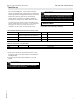
Additional Information Vitocell 100-V Installation Instructions Pressure Drop Information Pressure drop on heating water side (primary circuit) Pressure drop Pressure drop Pressure drop on domestic hot water side (secondary circuit) Flow rate Flow rate 5608 487 v1.
Additional Information Vitocell 100-V Installation Instructions Inspection Opening Inspection opening for 79 USG (300 L) tank Inspection opening for 120 USG (450 L) tank Post Installation Service binder 1. File all Parts Lists, Operating and Service Instructions in the Service Binder. Start-up information DHW Tank Start-up/Service Instructions 2. Install a protective hanging case near the boiler and store the Service Binder in this location. 22 5608 487 v1.
5608 487 v1.
Vitocell 100-V Installation Instructions 5608 487 v1.2 Technical information subject to change without notice. Printed on environmentally friendly (recycled and recyclable) paper.