
Unit installation


Vitocrossal 300, CT3 Series Installation
5285 873 - 02
26
Assembly
Observation Port Installation
Burner Installation
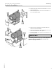
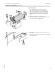
The combustion chamber is equipped with an observation
port for the burner flame and combustionchamber. The
standard equipment includes a plastic hose A, a brass
nipple B, and gaskets C. The brass nipple is to be
installed in the tube part of the observation port. One end
of the plastic hose attaches to the nipple.
The other end must be extended inside the burner housing
where it is attached to the blower housing.
A minute amount of air then purges the observation port
glass during burner operation and will keep the glass from
fogging up.
Legend
A Plastic hose
B Brass nipple
C Gaskets
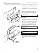
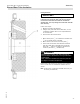
The proper burner plate for desired burner is supplied
by Viessmann
H Install the burner plate (part of the standard delivery).
H Once the burner has been mounted with the combustion
head, the door must be opened and any gap between
the combustion chamber door insulation and the
combustion head must be properly filled with supplied
Fiberfrax insulation material.
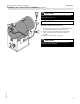
IMPORTANT
The combustion head of the burner must protrude through
the insulation of the combustion chamber door, and the
minimum of 5½ in. (140 mm) of the combustion head
length must be maintained (total length from flange).
In case a shorter combustion head is used, all combustion
results during all firing stages must be properly verified.
CAUTION
The temperature resistance of the combustion head
must be a minimum of 932° F (500° C).
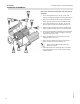
IMPORTANT
Due to the location of the observation port in the
combustion chamber door, it might be necessary to rotate
the burner 180°. The burner itself can be installed in this
position. It does not adversely affect the burner operation.
The gas piping will then be on top of the burner rather
than on the bottom (Weishaupt WG20 only).
For burner installation see instructions supplied
by burner manufacturer
See Burner Blast Tube Insulation Installation
Instructions on following page