Installation and service instructions VIESMANN for contractors Vitodens 100-W Type WB1C, 6.5 to 35.0 kW Wall mounted gas condensing boiler Natural gas and LPG version Gas Council no.: 41-819-20 - 22, 41-819-26 - 29 For applicability, see the last page VITODENS 100-W 5609 059 GB 2/2012 Please keep safe.
Safety instructions Safety instructions Please follow these safety instructions closely to prevent accidents and material losses. Safety instructions explained Danger This symbol warns against the risk of injury. ! Please note This symbol warns against the risk of material losses and environmental pollution. Note Details identified by the word "Note" contain additional information.
Safety instructions Safety instructions (cont.) If you smell flue gas Danger Flue gas can lead to life-threatening poisoning. ■ Shut down the heating system. ■ Ventilate the boiler room. ■ Close all doors leading to the living space. Working on the system ■ When using gas as fuel, also close the main gas shut-off valve and safeguard against unauthorised reopening. ■ Isolate the system from the power supply and check that it is no longer 'live', e.g.
Index Index Installation instructions Product information........................................................................................... 6 Preparing for installation................................................................................... 7 Installation sequence Fitting the boiler and making connections............................................................ 10 Opening the control unit casing............................................................................
Index Index (cont.) Certificates Declaration of conformity...................................................................................... 80 5609 059 GB Keyword index....................................................................................................
Product information Product information Vitodens 100-W, type WB1C Conversion for other countries The Vitodens 100-W should generally only be delivered to those countries specified on the type plate. For deliveries to alternative countries, an approved contractor, on his own initiative, must arrange individual approval in accordance with the law of the country in question.
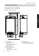
Preparing for installation Preparing for installation Preparing the boiler installation Dimensions and connections 156 350 860 700 Installation 68 5 250 400 A B CD E 5609 059 GB 58 58 123 123 150 F A Heating flow B Gas condensing boiler: Cylinder flow Gas condensing combi boiler: Domestic hot water C Gas connection D Gas condensing boiler: Cylinder return Gas condensing combi boiler: Cold water 34 125 E Heating return F Condensate drain/safety valve drain: Plastic hose 7 22 mm 7
Preparing for installation Preparing for installation (cont.
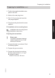
Preparing for installation Preparing for installation (cont.) 1. Position the supplied installation template on the wall. 2. Mark out the rawl plug holes. 3. Drill 7 10 mm holes and insert the rawl plugs supplied. Installation 4. Fit wall mounting bracket with screws supplied. Fit installation aid or mounting frame Installation aid or mounting frame installation instructions Preparing the connections ! Please note To prevent equipment damage, install all pipework free of load and torque stresses. 1.
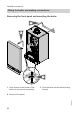
Installation sequence Fitting the boiler and making connections Removing the front panel and mounting the boiler 3. 2. 1. 2x 1. Undo screws at the bottom of the boiler; do not remove completely. 3. Hook the boiler into the wall mounting bracket. 5609 059 GB 2. Remove front panel.
Installation sequence Fitting the boiler and making connections (cont.) Making connections on the water side Gas condensing boiler Installation For fittings on the heating water side and DHW side, see separate installation instructions.
Installation sequence Fitting the boiler and making connections (cont.) Gas condensing combi boiler D E B F A C F Filling loop Gas connection 1. Connect gas shut-off valve to connection A.
Installation sequence Fitting the boiler and making connections (cont.) Note For the tightness test, use only suitable and approved leak detection agents (EN 14291) and devices. Leak detection agents with unsuitable constituents (e.g. nitrites, sulphides) can lead to material damage. Remove residues of the leak detection agent after testing. ! Please note Excessive test pressure may damage the boiler and the gas valve. Max. test pressure 150 mbar.
Installation sequence Fitting the boiler and making connections (cont.) Connection, safety valve and condensate drain ■ If the condensate pipe is routed outside the building, use a pipe of at least 7 30 mm and insulate it against frost. Avoid long outdoor pipework. ! A ■ Observe local building regulations. Connect the condensate pipe A with a constant fall and a pipe vent to the public sewage system. Observe the local waste water regulations. Note Fill the siphon with water before commissioning.
Installation sequence Fitting the boiler and making connections (cont.) Filling the siphon with water Fill the flue outlet with a minimum of 0.3 l of water. Please note At commissioning, flue gas may be emitted from the condensate drain. Fill the siphon with water before commissioning. Installation ! Flue and ventilation air connection Connect the balanced flue. During installation and positioning of the flue system, observe building regulations part L and BS 5440.
Installation sequence Opening the control unit casing 2. 3. 4x 1. Please note Electronic assemblies can be damaged by electrostatic discharge. Before beginning work, touch earthed objects, such as heating or water pipes, to discharge static loads.
Installation sequence Electrical connections X21 D X7 GAS PUMP ?LN 1 LN X20 E F % Installation C X1 FAN 4 3 2 1 OT A B B C D E OpenTherm device Connecting cable (accessory) Jumper Power supply (230 V, 50 Hz). See page 21. F Vitotrol 100 or on-site room temperature controller (230 V switched input) Remove jumper D when making this connection.
Installation sequence Electrical connections (cont.) Connection of room temperature controller and DHW cylinder with 230 V cylinder temperature controller C % A E D Cylinder temperature controller 230 V E Room thermostat 5609 059 GB A Junction box, cylinder demand B Jumper, remove when making this connection C Power supply (230 V, 50 Hz). See page 21.
Installation sequence Electrical connections (cont.) C % A Installation Connection of room temperature controller with time switch and DHW cylinder with 2-way valve and 230 V cylinder temperature controller H D M 1~ E G 5609 059 GB F A Junction box, cylinder demand B Jumper, remove when making this connection C Power supply (230 V, 50 Hz). See page 21.
Installation sequence Electrical connections (cont.) Cable entry B A A Power cable, remote control connecting cable B LV leads (sensor leads) Outside temperature sensor (accessory) 1. Fit outside temperature sensor. 3. Connect the outside temperature sensor to terminals 3 and 4. 5609 059 GB Installation site: ■ North or north-westerly wall, 2 to 2.
Installation sequence Electrical connections (cont.) Power supply Danger Incorrectly executed electrical installations can lead to injury from electrical current and result in equipment damage. Connect the power supply and implement all safety measures (e.g.
Installation sequence Electrical connections (cont.) Routing connecting cables and closing control unit ! Please note Connecting cables will be damaged if they touch hot components. When routing and securing cables/leads on site, ensure that the maximum permissible temperatures for these cables/leads are not exceeded. 3. 2. 5609 059 GB 1.
Commissioning, inspection, maintenance Steps - commissioning, inspection and maintenance For further information regarding the individual steps, see the page indicated Commissioning steps Inspection steps Maintenance steps • • • • • • • • 1. Filling the heating system.............................................. 24 2. Venting the boiler by flushing....................................... 26 3. Changing to operation with LPG................................... 27 4.
Commissioning, inspection, maintenance Further details regarding the individual steps Filling the heating system ! Please note Unsuitable fill water increases the level of deposits and corrosion and may lead to boiler damage. ■ Thoroughly flush the entire heating system prior to filling it. ■ Only use fill water of potable quality. ■ Soften fill water harder than 300 ppm. ■ An antifreeze additive suitable for heating systems can be added to the fill water. 1. Close the gas shut-off valve. 2.
Commissioning, inspection, maintenance Further details regarding the individual steps (cont.) Gas condensing boiler B C A 1. Open shut-off valves A and (if fitted) B. 2. Connect fill hose to valve C and open valve C. 3. Fill heating system [a removable filling loop with double check valve must be used in UK] (system pressure 0.8 to 1.2 bar). 4. Close valve C. close open Gas condensing combi boiler 1. Open shut-off valves A and (if fitted) B. Note The cold water supply must be open. 3.
Commissioning, inspection, maintenance Further details regarding the individual steps (cont.) Venting the boiler by flushing Gas condensing boiler 1. Connect the drain hose on shut-off valve A to a drain. A 2. Close shut-off valve B. 3. Open valves A and C and flush at mains pressure, until no sound of escaping air can be heard. 4. First close valve A and then valve C. 5. Adjust operating pressure ≥ 0.8 bar with valve C. 6. Open shut-off valve B. 7. Disconnect drain hose and put to one side.
Commissioning, inspection, maintenance Further details regarding the individual steps (cont.) Gas condensing boiler 1. Connect the drain hose on shut-off valve A to a drain. A 2. Close shut-off valve B. 3. Open valves A, C and D and flush at mains pressure, until no sound of escaping air can be heard. 4. First close valve A and then valves C and D. 5. Adjust operating pressure ≥ 0.8 bar with valves C and D. 6. Open shut-off valve B. 7. Disconnect drain hose and put to one side.
Commissioning, inspection, maintenance Further details regarding the individual steps (cont.) Checking the static and supply pressure Danger CO build-up as a result of incorrect burner adjustment can have serious health implications. Carry out a CO test before and after work on gas appliances. Operation with LPG Flush the LPG tank twice during commissioning or replacement. Purge the tank and gas supply line thoroughly after flushing. A 4. Check the static pressure. Set value: max. 57.5 mbar 5.
Commissioning, inspection, maintenance Further details regarding the individual steps (cont.) 9. Open the gas shut-off valve and start the appliance. Danger Gas escaping from the test nipple leads to a risk of explosion. Check gas tightness at test nipple A. Supply pressure (flow pressure) for natural gas for LPG below 17.4 mbar below 25 mbar 17.4 to 25 mbar above 25 mbar 25 to 47 mbar above 47 mbar Note The maximum pressure drop between the gas shut-off valve and test nipple A at the gas train is 0.
Commissioning, inspection, maintenance Further details regarding the individual steps (cont.) 4. Within 2 s, turn rotary selector "tw" to the top left range. The display shows "r", "w", "A", and the selected correction factor flashes. In the delivered condition, factor 0 has been set. 5. Within 15 s, set rotary selector "tr" to the required correction factor. 6. The set correction factor is saved when the value stops flashing, and the control unit returns to standard mode.
Commissioning, inspection, maintenance Further details regarding the individual steps (cont.) 2. Turn rotary selector "tr" fully clockwise for less than 2 s and then back into the r.h. control range. "SERV" and "A" appear on the display. r 3. Select the required max. heating output with rotary selector "tr". Bars for the selected heating output flash on the display. °C 60 A Service ■ Position 1 (1 bar) = lower heating output. ■ Position 6 (5 bars) = upper heating output. 5609 059 GB 4.
Commissioning, inspection, maintenance Further details regarding the individual steps (cont.) 5. Transfer selected heating output: Turn rotary selector "tw" fully clockwise for less than 2 s and then back into the r.h. control range. During the transfer, the display shows "– . – . –". 6. Shut down the boiler. Matching the circulation pump to the heating system Only for gas condensing combi boilers: In the delivered condition, the circulation pump in heating mode is set to stage 1.
Commissioning, inspection, maintenance Further details regarding the individual steps (cont.) 1. Turn ON/OFF switch ON. 2. Turn both rotary selectors "tw" and "tr" simultaneously into their respective central positions. "SERV" appears on the display. r 3. Within 2 s, turn rotary selector "tr" to the top right range. "r" appears on the display and the set value flashes. r 5609 059 GB 5. The set operating mode is saved when the value stops flashing, and the control unit returns to standard mode.
Commissioning, inspection, maintenance Further details regarding the individual steps (cont.) Checking the CO2 content The Vitodens 100-W is factory-set for natural gas. During commissioning or maintenance, the CO2 and CO have to be measured at the boiler flue adaptor test point to check the flue integrity. Subject to the Wobbe index, the CO2 content fluctuates between 7.4 % and 10.5 %. CO of up to 500 ppm during ignition is acceptable.
Commissioning, inspection, maintenance Further details regarding the individual steps (cont.) 04. Adjust the upper heating output: Turn rotary selector "tr" to the control range on the right until the display shows 5 bars for the upper heating output. 05. Check the CO2 content for the upper heating output. The CO2 content must be between 7.0 and 10.5 %. 06. Adjust the lower heating output: Turn rotary selector "tr" to the control range on the left until the display shows 1 bar for the lower heating output.
Commissioning, inspection, maintenance Further details regarding the individual steps (cont.) 11. Turn both rotary selectors "tw" and "tr" into their respective original positions. Burner removal F4x C E D B A 1. Switch the power OFF. 4. Pull venturi extension D from the fan. 2. Shut off the gas supply. 36 5609 059 GB 5. Undo gas supply pipe fitting E. 3. Pull power cables from fan motor A, gas valve B and electrodes C.
Commissioning, inspection, maintenance Further details regarding the individual steps (cont.) 6. Undo four screws F and remove the burner. ! Please note Prevent damage. Never rest the burner on the burner gauze assembly. Checking the burner gasket and burner gauze assembly Check burner gasket A for damage and replace if required. Replace the burner gauze assembly if it is damaged. E D C A Service 2x B 5609 059 GB 1. Remove electrode B. 2.
Commissioning, inspection, maintenance Further details regarding the individual steps (cont.) 4. Insert and secure new burner gauze assembly D with new gasket E. ! 6. Fit electrode B. ! Please note Tighten screws sufficiently to prevent the components being damaged and to ensure they function correctly. Please note Tighten screws sufficiently to prevent the components being damaged and to ensure they function correctly. 5. Refit thermal insulation ring C.
Commissioning, inspection, maintenance Further details regarding the individual steps (cont.) Cleaning the heat exchanger 1. ! Please note Scratches on parts that are in contact with flue gas can lead to corrosion. Never use brushes to clean the heat exchanger. Use a vacuum cleaner to remove residues from heat exchanger A inside the combustion chamber. 2.
Commissioning, inspection, maintenance Further details regarding the individual steps (cont.) 7. Check that condensate can drain freely and that the connections are tight.
Commissioning, inspection, maintenance Further details regarding the individual steps (cont.) 1. Fit the burner and tighten four screws A diagonally. ! 6. Check the gas connections for tightness. Danger Escaping gas leads to a risk of explosion. Check all fittings for gas tightness. Please note Tighten screws sufficiently to prevent the components being damaged and to ensure they function correctly. 2. Insert new gasket and tighten the fittings on gas supply pipe B. 3.
Commissioning, inspection, maintenance Further details regarding the individual steps (cont.) Checking gas equipment for tightness at operating pressure Danger Escaping gas leads to a risk of explosion. Check gas equipment for tightness. ! Please note The use of leak detection spray can result in incorrect functions. Leak detection spray must not reach electrical contacts or seal diaphragm openings on the gas valve. Fitting the front panel 1. 2. 1. Hook the front panel into place. 42 2.
Commissioning, inspection, maintenance Further details regarding the individual steps (cont.) Instructing the system user 5609 059 GB Service The system installer must hand the operating instructions to the system user and instruct the user in the operation of the system.
Troubleshooting Function sequence and possible faults Display No Control unit issues a heat demand Action Increase set value and ensure heat is drawn off Yes Fan starts No After approx.
Troubleshooting Function sequence and possible faults (cont.) Yes Burner in operation No Stops below the set boiler water temperature and restarts immediately Check the flue system for tightness (flue gas recirculation), check the gas flow pressure Fault messages on the display Displayed fault code 10 18 30 38 Measures Check the outside temperature sensor and lead (see page 49). Check the outside temperature sensor and lead (see page 49). Check the boiler water temperature sensor (see page 51).
Troubleshooting Fault messages on the display (cont.
Troubleshooting Fault messages on the display (cont.) F3 Burner in a fault state Flame signal is already present at burner start F4 Burner in a fault state No flame signal F8 Burner in a fault state Fuel valve closes too late F9 Burner in a fault state Fan speed too low during burner start FA Burner in a fault state Fan not at standstill FC Burner blocked Electrical fan control (control unit) faulty Measures Check heating system fill level. Check circulation pump. Vent the system.
Troubleshooting Fault messages on the display (cont.) Displayed fault code Fd FF System characteris- Cause tics Burner blocked Fault, burner control unit Burner blocked Fault, burner control unit Measures Check ignition electrodes and connecting cables. Check whether a strong interference (EMC) field exists near the appliance. Press "Reset" (see page 48). Replace control unit if fault persists. Check ignition electrodes and connecting cables.
Troubleshooting Repairs Removing the front panel 2. 1. 1. Undo screws at the bottom of the boiler; do not remove completely. Service 2x 2. Remove front panel. Outside temperature sensor 5609 059 GB 1. Open the control unit casing. See page 16.
Troubleshooting Repairs (cont.) 2. Disconnect leads from outside temperature sensor. X21 X7 X20 4 3 2 1 20 3. Check the sensor resistance and compare it with the curve. 4. Replace the sensor in the case of severe deviation.
Troubleshooting Repairs (cont.) Boiler water temperature sensor 1. Pull the leads from boiler water temperature sensor A and check the resistance.
Troubleshooting Repairs (cont.) Resistance in kΩ 20 2. Check the sensor resistance and compare it with the curve. 10 8 6 4 3. In case of severe deviation, drain boiler on the heating water side and replace the sensor. 2 1 0.8 0.6 0.4 10 30 50 70 90 110 Temperature in °C Danger The boiler water temperature sensor is immersed in the heating water (risk of scalding). Drain the boiler before replacing the sensor. Checking cylinder temperature sensor (gas condensing boiler) 1.
Troubleshooting Repairs (cont.) Resistance in kΩ 20 2. Compare the sensor resistance with the curve. 10 8 6 4 3. Replace the sensor in the case of severe deviation. 2 1 0.8 0.6 0.4 10 30 50 70 90 110 Temperature in °C Checking the temperature limiter A If the burner control unit cannot be reset after a fault shutdown, although the boiler water temperature is below approx. 95 °C, check the temperature limiter. 1. Pull the leads from temperature limiter A. 3. Remove the faulty temperature limiter.
Troubleshooting Repairs (cont.) Checking the outlet temperature sensor (gas condensing combi boiler) 1. Pull leads from outlet temperature sensor A. 2. Check the sensor resistance and compare it with the curve. A 10 8 6 4 2 1 0.8 0.6 0.4 10 30 50 70 90 110 Temperature in °C 3. Replace the sensor in the case of severe deviation. Note Water can leak when replacing the outlet temperature sensor. Shut off the cold water supply. Drain the DHW line and the plate heat exchanger (DHW side).
Troubleshooting Repairs (cont.) Checking the flue gas temperature sensor 1. Pull leads from flue gas temperature sensor A. 2. Check the sensor resistance and compare it with the curve.
Troubleshooting Repairs (cont.) Resistance in kΩ 20 3. Replace the sensor in the case of severe deviation. 10 8 6 4 2 1 0.8 0.6 0.4 10 30 50 70 90 110 Temperature in °C Replacing flow limiter (gas condensing combi boiler) A 1. Drain the boiler from the DHW side. 2. Pivot the control unit downwards. B C 3. Undo screws A. 4. Remove cap B. 5. Remove faulty flow limiter C. 6. Select new flow limiter C corresponding to boiler serial no. (see type plate) and the following table. 7.
Troubleshooting Repairs (cont.) Checking or replacing the plate heat exchanger (gas condensing combi boiler) D D E F H G A B C G Cold water H Domestic hot water 1. Shut off and drain the boiler on the heating water and the DHW side. 4. Turn adaptor B with servomotor A 1/8 of a turn anti-clockwise and remove. Service E Heating water flow F Heating water return 2. Flip down control unit. 5609 059 GB 3. Push servomotor A slightly upwards.
Troubleshooting Repairs (cont.) 5. Remove two screws C from the plate heat exchanger and remove plate heat exchanger D with gaskets. 7. Check the heating water side for contamination and if required clean or replace the plate heat exchanger. 8. Install in reverse order with new gaskets. Note During removal, small amounts of water may trickle out and escape from the plate heat exchanger. 6. Check the DHW side for scaling and if required clean or replace the plate heat exchanger.
Gas type conversion Converting from LPG to natural gas Removing gas restrictor B F A C ED 2. Remove union nut B. 3. Undo two screws C and remove gas train A. 4. Remove gas restrictor D from gas train A. 5. Mount gas train A with new gaskets E and F. 5609 059 GB ! 6. Remove or void gas type sticker on the top of the boiler (next to the type plate). 7. Start the boiler and check for leaks. Danger Escaping gas leads to a risk of explosion. Check gas equipment for tightness.
Gas type conversion Converting from LPG to natural gas (cont.) Converting the gas type at the control unit 1. Turn ON/OFF switch ON. 2. Turn both rotary selectors "tw" and "tr" simultaneously into their respective central positions. "SERV" appears on the display. r 3. Turn rotary selector "tr" fully anticlockwise within 2 s. The set value and "A" flash on the display. r 4. Adjust the control unit to natural gas or LPG by turning rotary selector "tw".
Control unit Functions and operating conditions in weather-compensated mode In weather-compensated mode, the boiler water temperature is regulated subject to the outside temperature.
Designs E D A B 62 Stepper motor diverter valve Ignition/ionisation C Vitotrol 100 type UTA or on-site room temperature controller (switched 230 V input) 5609 059 GB M L K H G A F B C Connection and wiring diagram
Designs Connection and wiring diagram (cont.
Parts lists Ordering parts Obtain standard parts from your local supplier. 5609 059 GB The following information is required: ■ Serial no.
Parts lists Overview of the assemblies A B C Service D E F D Control unit assembly E Heat cell assembly F Miscellaneous assembly 5609 059 GB A Type plate B Sheet metal parts assembly C Hydraulic assembly 65
Parts lists Sheet metal parts assembly 0001 0002 0003 0004 Front panel Profiled seal Logo Strain relief upper part 0005 0006 0007 0008 Air box floor Diaphragm grommets (set) Wall mounting bracket Control flap 0007 0002 0001 0002 0008 0005 0006 5609 059 GB 0004 66
Parts lists Heat cell assembly 0001 0002 0003 0004 0005 0006 0007 0008 Gasket DN 60 Boiler flue connection Boiler flue connection plug Flue gas gasket Flue gas temperature sensor Heat exchanger Condensate hose Siphon 0009 0010 0011 0012 0013 0014 0015 0016 Tee Gas pipe Gasket 17 x 24 x 2 (set) Burner Thermal insulation block Heat exchanger mounting (set) O-ring gasket set 20.6 x 2.
Parts lists Burner assembly Burner gasket Insulation ring Cylinder burner gauze assembly Burner gauze assembly gasket Burner door Ionisation electrode gasket Ignition and ionisation electrode Burner door flange gasket 0009 0010 0012 0013 0014 0015 0016 Radial fan Gas valve Venturi extension Gasket A 17 x 24 x 2 (set) Conversion kit G31 Gasket set G27 (not GB) Conversion kit G2.
Parts lists Burner assembly (cont.
Parts lists Hydraulic assembly 0011 0012 0013 0014 0015 0016 0017 0018 0019 0020 0021 Air vent valve G ⅜ Temperature sensor Round sealing ring 8 x 2 Moulded hose heating water flow Clip Ø 18 (5 pce) O-ring 17 x 4 (5 pce) Pressure gauge Clip Ø 8 (5 pce) Hose connector adaptor Thermal circuit breaker Heating water flow connection elbow 0022 Hydraulics 5609 059 GB 0001 Diaphragm expansion vessel 0002 Support block, diaphragm expansion vessel 0003 Gasket A 10 x 15 x 1.
Parts lists Hydraulic assembly (cont.
Parts lists System boiler hydraulic assembly Air vent valve O-ring 34 x 3 (5 pce) Gasket set, plate heat exchanger Safety valve 3 bar Special safety valve clip (5 pce) Pump motor Bypass cartridge Clip Ø 16 (5 pce) Stepper motor adaptor 0015 0016 0020 0021 0022 0023 0026 0031 Linear stepper motor Oval cap seal (5 pce) Hydraulics O-ring 19.8 x 3.
Parts lists System boiler hydraulic assembly (cont.
Parts lists Combi hydraulic assembly Air vent valve O-ring 34 x 3 (5 pce) Plate heat exchanger Gasket set, plate heat exchanger Safety valve Clip Ø 8 (5 pce) Safety valve clip (5 pce) Pump motor Bypass cartridge Flow sensor Clip Ø 10 (5 pce) Clip Ø 16 (5 pce) Stepper motor adaptor 0015 0016 0017 0018 0020 0021 0022 0023 0026 0027 0029 0031 Linear stepper motor Oval cap seal (5 pce) Water volume controller Temperature sensor Hydraulics O-ring 19.8 x 3.
Parts lists Combi hydraulic assembly (cont.
Parts lists Control unit assembly (cont.) 0005 Cable harness X20 0006 Ignition cable with elbow plug 5 kΩ 0007 Gas valve cable 0008 Fan connecting cable 0009 Cable harness stepper motor 0010 Fuse 2.
Parts lists Miscellaneous assembly 0001 Spray paint, Vitowhite 0002 Touch-up paint stick, Vitowhite 0003 Special grease 0004 Operating instructions 0005 Installation and service instructions 0001 0002 0003 0004 5609 059 GB Service 0005 77
Specification Specification Rated voltage: Rated frequency: Rated current: Safety category: IP rating: 230 V~ 50 Hz 2.0 A~ I IP X4 to EN 60529 Temperature limiter setting: Backup fuse (power supply): 100 °C (fixed) 3A Permissible ambient temperature ■ during operation: 0 to +40 °C ■ during storage and transport: -20 to +65 °C Gas boiler, category II 2H3P Rated heating output range in heating mode TV/TR 50/30 °C kW TV/TR80/60 °C kW 6.5 – 19 5.9 – 17.3 6.5 – 26 5.9 – 23.7 8.8 – 30 8.0 – 27.3 8.
Specification Specification (cont.) Rated heating output range in heating mode TV/TR 50/30 °C TV/TR80/60 °C l/min 6.5 – 19 5.9 – 17.3 — l/min — 6.5 – 26 5.9 – 23.7 10.6 8.8 – 30 8.0 – 27.3 12.3 8.8 – 35 8.0 – 31.9 10.0 12.0 _-0085BT0029 14.0 14.3 5609 059 GB Service Rated water volume at ΔT 35 K (to EN 13203) Set flow rate (max.
Certificates Declaration of conformity Declaration of Conformity for the Vitodens 100-W We, Viessmann Werke GmbH&Co KG, D-35107 Allendorf, confirm as sole responsible body that the product Vitodens 100-W complies with the following standards: EN 297 EN 483 EN 625 EN 677 EN 806 EN 12 897 EN 55 014-1 EN 55 014-2 EN 60 335-1 EN 60 335-2-102 EN 61 000-3-2 EN 61 000-3-3 EN 62 223 In accordance with the following Directives, this product is designated with _-0085: 92/42/EEC 2004/108/EC 2006/95/EC 2009/142/EC
Keyword index Keyword index B Boiler water temperature sensor .......51 Burner gasket.....................................37 Burner gauze assembly.....................37 Burner installation..............................40 Burner removal..................................36 C Cleaning the combustion chamber....39 Cleaning the heat exchanger.............39 Commissioning..................................24 Condensate........................................14 Condensate drain.........................
Keyword index Keyword index (cont.) T Temperature limiter............................53 Troubleshooting.................................49 W Wall mounting......................................8 Weather-compensated mode.............61 5609 059 GB V Ventilation air pipe.............................15 Venting...............................................
5609 059 GB
7499424 7499428 Viessmann Werke GmbH&Co KG D-35107 Allendorf Telephone: +49 6452 70-0 Fax: +49 6452 70-2780 www.viessmann.com 84 7499425 7499429 7499426 Viessmann Limited Hortonwood 30, Telford Shropshire, TF1 7YP, GB Telephone: +44 1952 675000 Fax: +44 1952 675040 E-mail: info-uk@viessmann.com Subject to technical modifications. Serial No.