VIESMANN VITODENS Gas condensing boiler 3.8 to 35.0 kW Technical guide VITODENS 222-F Type FS2B Gas condensing storage combi boiler, 4.8 to 35.0 kW, for natural gas and LPG VITODENS 242-F Type FB2B Compact Energy Tower for combined gas condensing/ solar thermal systems, 4.8 to 26.0 kW, for natural gas and LPG VITODENS 333-F Type FS3B and FR3B Gas condensing storage combi boiler, 3.8 to 26.
Index Index Vitodens 222-F, type FS2B 1.1 Product description ....................................................................................................... 1.2 Specification ................................................................................................................. 4 6 2. Vitodens 242-F, type FB2B 2.1 Product description ....................................................................................................... 13 2.2 Specification ...........................
Index (cont.) 7.3 Accessories for the Vitotronic ....................................................................................... ■ Allocation to control unit types .................................................................................. ■ Vitotrol 100, type UTA ............................................................................................... ■ Vitotrol 100, type UTDB ............................................................................................
Vitodens 222-F, type FS2B 1.
Vitodens 222-F, type FS2B (cont.) Accessories required (order separately) Installation on unfinished walls ■ Connection set for installation on unfinished walls or ■ Assembly kit with mixer Approved quality CE designation according to current EC Directives Meets the requirements for the "Blue Angel" certificate of environmental excellence to RAL UZ 61.
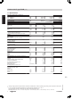
Vitodens 222-F, type FS2B (cont.) 1.2 Specification Gas boiler, types B and C, category II2N3P Rated output range (details to DIN EN 677) TV/TR = 50/30 °C TV/TR = 80/60 °C Rated output for DHW heating Rated heat input Product ID IP rating Gas supply pressure Natural gas LPG Max. permissible gas supply pressure*1 Natural gas LPG Power consumption (in the delivered condition) – with two-stage circulation pump – with variable speed high efficiency DC pump Weight Heat exchanger capacity Max.
Vitodens 222-F, type FS2B (cont.
Vitodens 222-F, type FS2B (cont.) 50 1 c d 40 100 80 50 46 595 224 50 569 b a 140 50 600 Rated output range kW 4.8 to 19 6.5 to 26 8.
Vitodens 222-F, type FS2B (cont.) Note The adjustable feet give all height measurements a tolerance of +15 mm. 1 Two-stage heating circuit pump in the Vitodens 222-F Rated boiler output Type Rated voltage Power consumption kW 4.8 - 26.0 VI UPSO 15-60 230 60 70 V~ W W Stage 1 Stage 2 8.8 - 35.0 VI UPSO 15-70 230 70 90 Residual head of the integral circulation pump Vitodens 222-F, 4.8 - 26.
Vitodens 222-F, type FS2B (cont.) Vitodens 222-F, 8.8 - 35.0 kW 40 1 400 350 30 300 250 20 C 200 kPa 10 0 Residual head in mbar 150 B 100 50 0 A 0 100 200 Flow rate in l/h 300 400 500 600 700 800 900 1000 1100 1200 1300 1400 A Stage 1 B Stage 2 C Upper operational limit Variable speed heating circuit pump in the Vitodens 222-F The integral circulation pump is a highly efficient DC pump with substantially lower power consumption than conventional pumps.
Vitodens 222-F, type FS2B (cont.) Residual head of the integral circulation pump Vitodens 222-F, 4.8 - 26.
Vitodens 222-F, type FS2B (cont.) Vitodens 222-F, 8.8 - 35.
Vitodens 242-F, type FB2B 2.
Vitodens 242-F, type FB2B (cont.) Accessories required (order separately) Installation on unfinished walls ■ Connection set for installation on unfinished walls or ■ Assembly kit with mixer Approved quality CE designation according to current EC Directives Meets the requirements for the "Blue Angel" certificate of environmental excellence to RAL UZ 61.
Vitodens 242-F, type FB2B (cont.) 2.2 Specification 5822 431 GB Gas boiler, types B and C, category II2N3P Rated output range (details to DIN EN 677) TV/TR = 50/30 °C TV/TR = 80/60 °C Rated output for DHW heating Rated heat input Product ID IP rating Gas supply pressure Natural gas LPG Max. permissible gas supply pressure*4 Natural gas LPG Power consumption (in the delivered condition) Weight – Total (with casing) – Heat cell module – Cylinder module Heat exchanger capacity Max.
Vitodens 242-F, type FB2B (cont.
Vitodens 242-F, type FB2B (cont.
Vitodens 242-F, type FB2B (cont.) Note The dimensioned drawing shows example fittings for upward connection and connection to the left/right, for installation on finished walls. Order the connection sets separately as accessories. For the dimensions of the individual connection sets, see the technical guide. If using the connection set (for downward connection) with a premounting bracket for installation on finished walls, maintain a wall clearance of 70 mm.
Vitodens 242-F, type FB2B (cont.) Residual head of the integral solar circuit pump 800 70 700 60 600 50 40 30 kPa 20 10 0 Residual head in mbar 80 500 400 300 200 100 0 A 0 Flow rate in l/h B 500 2 C 1000 1500 A Stage 1 B Stage 2 C Stage 3 5822 431 GB 1310 810 0 60 Handling the Vitodens 242-F in tight spaces If required the heat cell and cylinder can be separated for easier handling at the installation location. For the weight of the individual parts, see the specification.
Vitodens 333-F, type FS3B 3.1 Product description A Stainless steel Inox-Radial heat exchanger for high operational reliability, a long service life and high output in the smallest space B Modulating MatriX gas burner for extremely clean combustion C Integral diaphragm expansion vessel D Digital boiler control unit E Integral, variable speed high efficiency DC pump F Stainless steel DHW primary store 3 Recommended applications ■ Installations in detached and terraced houses ■ New build (e.g.
Vitodens 333-F, type FS3B (cont.) Set up for operation with natural gas. A conversion within the gas group E/LL is not required. The conversion to LPG is made at the gas valve (a conversion kit is not required).
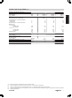
Vitodens 333-F, type FS3B (cont.) 3.2 Specification *7 *8 22 kW kW kW kW 3.8-13.0 3.5-11.8 3.5-16.0 3.6-16.7 3.8-19.0 3.5-17.2 3.5-17.2 3.6-17.9 CE-0085BU0052 IP X4D in accordance with DIN EN 60529 5.2-26.0 4.7-23.7 4.7-23.7 4.9-24.7 mbar mbar 20 50 20 50 20 50 mbar mbar W 25.0 57.5 57 25.0 57.5 61 25.0 57.5 68 kg litres l/h 110 3.8 1000 110 3.8 1200 113 5.0 1400 l/h 507 740 1019 litres bar bar 12 0.75 3 12 0.75 3 12 0.
Vitodens 333-F, type FS3B (cont.
Vitodens 333-F, type FS3B (cont.) 50 E F B D B C F A E A C D G K G 1425 100 80 1485 40 50 3 H 745 140 569 46 G D C E B 50 595 A a 50 F 600 Heating flow R ¾ DHW R ½ Gas connection R ½ Cold water R ½ Heating return R ¾ DHW circulation R ½ (separate accessory) Condensate drain to the back into the wall Side condensate drain Cable entry area Rated output range kW 3.8 to 13 3.8 to 19 5.
Vitodens 333-F, type FS3B (cont.) Variable speed heating circuit pump in the Vitodens 333-F The integral circulation pump is a highly efficient DC pump with substantially lower power consumption than conventional pumps. The pump speed and consequently the pump rate is regulated subject to the outside temperature and the switching times for heating or reduced mode. The control unit transmits the current default speed via an internal data BUS to the circulation pump.
Vitodens 333-F, type FS3B (cont.) Vitodens 333-F, 5.
Vitodens 333-F, type FR3B 4.
Vitodens 333-F, type FR3B (cont.
Vitodens 333-F, type FR3B (cont.) 4.2 Specification 5822 431 GB Gas boiler, types B and C, category II2N3P Rated output range (details to DIN EN 677) TV/TR = 50/30 °C TV/TR = 80/60 °C Rated output for DHW heating Rated heat input Product ID IP rating Gas supply pressure Natural gas LPG Max. permissible gas supply pressure*10 Natural gas LPG Power consumption in the delivered condition (incl. circulation pump) Weight Heat exchanger capacity Max.
Vitodens 333-F, type FR3B (cont.
Vitodens 333-F, type FR3B (cont.) 50 E F B D B C F A E A C D G K G 50 1625 100 80 1685 40 140 945 H 46 569 4 G D C E B 50 595 A a 50 F 600 5822 431 GB A B C D E F G H K Heating flow R ¾ DHW R ½ Gas connection R ½ Cold water R ½ Heating return R ¾ DHW circulation R ½ (separate accessory) Condensate drain to the back into the wall Side condensate drain Cable entry area Rated output range kW 3.8 to 19 5.
Vitodens 333-F, type FR3B (cont.) Variable speed heating circuit pump in the Vitodens 333-F The integral circulation pump is a highly efficient DC pump with substantially lower power consumption than conventional pumps. The pump speed and consequently the pump rate is regulated subject to the outside temperature and the switching times for heating or reduced mode. The control unit transmits the current default speed via an internal data BUS to the circulation pump.
Vitodens 333-F, type FR3B (cont.) Vitodens 333-F, 5.
Installation accessories 5.1 Installation accessories Vitodens 222-F and Vitodens 333-F Connection set (for upward connection) for installation on finished walls Part no. 7348 566 Comprising: ■ Connecting pipes ■ Shut-off valves (R ¾) for heating water flow and return with boiler drain & fill valve ■ 2 connectors for DHW (R ½) ■ Gas shut-off valve (R ½) with thermally activated safety shut-off valve Connection set (for upward connection) with premounting bracket for installation on finished walls Part no.
Installation accessories (cont.) Assembly kit accessories Line regulating valve Part no. 7194 894 For hydraulically balancing the heating circuits. Contact temperature limiter Part no. 7425 493 Maximum temperature limiter for underfloor heating circuits. Contact temperature limiter with 1.5 m long connecting cable. Assembly kit with mixer ■ For installation on finished walls – with three-stage circulation pump: Part no. Z007 471 – With variable speed high efficiency DC pump: Part no.
Installation accessories (cont.) Residual head of the integral circulation pump for the heating circuit with mixer With variable speed high efficiency DC pump 600 50 500 40 400 30 20 kPa 10 0 Residual head in mbar 60 300 Max. 200 100 0 Min.
Installation accessories (cont.) 34 32 30 28 D 26 24 22 18 C 16 14 12 B 10 G 8 6 A 4 Output, heating circuit without mixer, in kW 2 A B C D E 0 8 4 2 C G 6 E F 0 0 1 2 3 4 5 6 Output in kW — heating circuit with mixer 8 Vitodens, 13 kW Vitodens, 19 kW Vitodens, 26 kW Vitodens, 35 kW Output range of the heating circuit without mixer without line regulating valve Calculating the transferable output (examples) ■ Vitodens 333-F, 3.8 to 19 kW.
Installation accessories (cont.) Note Vitodens with primary store or solar cylinder also requires an AM1 or EA1 extension for connection to the Vitotronic. ■ 10 bar Part no. 7351 842 ■ a 6 bar Part no. 7351 840 Valve/fittings cover Part no. 7352 257 For connection set for installation on unfinished walls. Not for use in conjunction with filling facility. Connection set DHW expansion vessel Part no. 7351 854 For installation in the Vitodens. Max.
Installation accessories (cont.) 310 Boiler plinth Part no. 7352 259 145 DN 40 Neutralising granulate Part no. 9524 670 (2 × 1.3 kg) 59 0 60 ■ For the installation of the Vitodens on unfinished floors ■ Adjustable height, for screed floors from 10 to 18 cm Transport aid Part no. 7425 341 2000 Part no. 7374 796 Automatic condensate lifting system for condensate with a pH value ≥ 2.7 from oil and gas condensing boilers. Components: ■ Condensate container 0.
Installation accessories (cont.) A C B B B B ■ Two-boiler system – 19 and 26 kW: Part no. Z008 384 – 35 kW: Part no. Z008 385 ■ Three-boiler system – 19 to 35 kW: Part no. Z008 386 ■ Four-boiler system – 19 to 35 kW: Part no.
Installation accessories (cont.) 5.2 Installation accessories Vitodens 242-F Connection set (for upward connection) for installation on finished walls Part no.
Installation accessories (cont.) ■ Mounting bracket ■ Connecting pipes ■ Shut-off valves (R ¾) for heating water flow and return with boiler drain & fill valve ■ 2 connectors for DHW (R ½) ■ 2 connectors for solar flow and return (R ¾) ■ Gas angle valve (R ½) with thermally activated safety shut-off valve Assembly kit with mixer ■ For installation on finished walls – with three-stage circulation pump: Part no. Z007 475 – With variable speed high efficiency DC pump: Part no.
Installation accessories (cont.
Installation accessories (cont.) With three-stage circulation pump 700 60 600 50 500 40 400 30 20 kPa 10 0 Residual head in mbar 70 300 200 100 0 0 100 200 Flow rate in l/h 300 400 500 600 700 800 900 1000 1100 1200 1300 1400 1500 1600 A Stage 1 B Stage 2 C Stage 3 Assembly kit scope The following diagram shows the relationship between the transferable outputs of the heating circuit with mixer and the heating circuit without mixer.
Installation accessories (cont.) D Output range of the heating circuit without mixer with line regulating valve E Example Calculating the transferable output (examples) ■ Vitodens, 19 kW. Supplying the heating circuit without mixer through the internal circulation pump in the Vitodens. 1.1. Apply the output of the heating circuit with mixer to the horizontal axis (example: 10 kW). 1.2. Extend the line vertically down to lower curve B. 1.3. Transfer the intersection horizontally to the l.h.
Installation accessories (cont.) ■ Control unit for pump operation, display of operating conditions and fault messages ■ 2 m long power cable with plug ■ Two 7 24 mm connection apertures for condensate inlet The standard delivery comprises: ■ 6 m long drain hose 7 14 x 2 mm ■ Non-return valve 148 Safety valve solar For integration in the Vitodens 242-F Part no. 7460 323 Response pressure: 6 bar Rp ½ - Rp ¾ 118 Automatic thermostatic mixing valve Part no.
Installation accessories (cont.) 70 Transport aid Part no. 7425 341 0 60 59 5 To make transportation of the boiler easier. ■ For the installation of the Vitodens on unfinished floors ■ Adjustable height, for screed floors from 10 to 18 cm ■ With spacer (for downward connection) for installation on finished walls Small softening system for heating water For filling heating circuits. See Vitoset pricelist. Plate heat exchanger flushing system Part no. 7373 005 For cleaning the plate heat exchanger.
Design information (cont.) It may, for example, be installed in recreation rooms, in other living space, in ancillary rooms without ventilation, in cupboards (open at the top) and recesses without maintaining minimum clearances to combustible parts as well as in attic rooms (pitched attics and ancillary rooms) where the balanced flue pipe can be directly routed through the roof.
Design information (cont.) Thermally activated safety shut-off valve According to paragraph 4, sect. 5 of the FeuVo '96 [Germany], thermally activated shut-off equipment, that isolates the gas supply if external temperatures exceed 100 ºC, must be installed in gas combustion equipment or in gas supply lines. These valves must isolate the gas supply for at least 30 minutes up to a temperature of 650 ºC. This should prevent the formation of explosive gas mixtures in the event of a fire.
Design information (cont.) Installation Vitodens 222-F and 333-F Connection sets (for upward connection) for installation on finished walls Connection set with premounting bracket for pre-assembly in unfinished buildings, part no. 7355 317 Connection set without premounting bracket, part no.
Design information (cont.) Connection set comprising: ■ Connection bracket (only for part no. 7355 317) ■ Connecting pipes ■ Shut-off valves for heating water flow and return with boiler drain & fill valve ■ 2 connectors for DHW ■ Gas shut-off valve with thermally activated safety shut-off valve Connection sets (for connection to the left or right) for installation on finished walls Connection set without premounting bracket, part no.
Design information (cont.) Note The adjustable feet give the height measurements of the connections a tolerance of + 15 mm. For connecting on-site lines on the gas, heating water and DHW sides from the left or right.
Design information (cont.) Note The adjustable feet give the height measurements of the connections a tolerance of + 15 mm. ■ Shut-off valves for heating water flow and return with boiler drain & fill valve ■ 2 connectors for DHW ■ Gas shut-off valve with thermally activated safety shut-off valve For connecting on-site lines on the gas, heating water and DHW sides from the left or right.
Design information (cont.) Type Vitodens 222-F, FS2B - 19 and 26 kW - 35 kW Vitodens 333-F, FS3B Vitodens 333-F, FR3B a mm b mm c mm For connecting on-site lines on the gas, heating water and DHW sides from below.
Design information (cont.) Type Vitodens 222-F, FS2B - 19 and 26 kW - 35 kW Vitodens 333-F, FS3B Vitodens 333-F, FR3B a mm b mm c mm 1475 1675 1475 1675 1496 1696 1496 1696 1752 1952 1782 1982 Note The adjustable feet give the height measurements of the connections a tolerance of + 15 mm. Note In place of the connection bend for cold water, a safety assembly (separate accessory) can be fitted.
Design information (cont.) E Gas connection R ½ F Cold water R ½ Type Vitodens 222-F, FS2B - 19 and 26 kW - 35 kW Vitodens 333-F, FS3B Vitodens 333-F, FR3B G Heating return, heating circuit without mixer R ¾ H Heating return, heating circuit with mixer R ¾ a mm b mm c mm d mm e mm 1477 1677 1477 1677 1580 1780 1580 1780 1602 1802 1602 1802 1672 1872 1672 1872 1725 1925 1725 1925 Note The adjustable feet give the height measurements of the connections a tolerance of + 15 mm.
Design information (cont.) Assembly kit with mixer – unfinished walls with mounting plate for pre-installation in unfinished buildings, part no.
Design information (cont.) Note The adjustable feet give the height measurements of the connections a tolerance of + 15 mm. For connecting on-site lines on the gas, heating water and DHW sides from within the wall.
Design information (cont.) Installation Vitodens 242-F Connection sets (for upward connection) for installation on finished walls Connection set with premounting bracket for pre-assembly in unfinished buildings, part no. 7351 778 Connection set without premounting bracket, part no.
Design information (cont.) Connection sets (for connection to the left or right) for installation on finished walls Connection set without premounting bracket, part no.
Design information (cont.) Connection set with premounting bracket for pre-assembly in unfinished buildings, part no.
Design information (cont.) Connection set with pre-mounting bracket for pre-assembly on finished walls in unfinished buildings, part no. 7354 669 440 330 220 55 50 K 70 a b c ABCDE FGH ABCDE FGH 6 F G H K b mm 1925 c mm 2102 A wall clearance of 70 mm is required behind the Vitodens. Note The adjustable feet give the height measurements of the connections a tolerance of + 15 mm.
Design information (cont.) Connection set with mounting bracket for pre-assembly on unfinished walls in unfinished buildings, part no.
Design information (cont.) Assembly kit with mixer for finished walls, part no.
Design information (cont.) ■ Cover with the same design as the appliance ■ Balanced flue extension, boiler flue connection Assembly kit with mixer – unfinished walls with mounting plate for pre-installation in unfinished buildings, part no.
Design information (cont.
Design information (cont.
Design information (cont.) 6.
Design information (cont.) DHW circulation DHW circulation pipes increase DHW convenience and reduce water consumption. These advantages result from the immediate availability of hot water at the tap/draw-off point. However, poor insulation of the DHW circulation line can lead to substantial heat losses. From a line length of 7 m and longer, we recommend the installation of a DHW circulation line with appropriate thermal insulation in accordance with the Energy Savings Order [Germany].
Design information (cont.) Neutralising system C A B A Condensate drain B Neutralising system C Venting via the roof The Vitodens can (if required) be supplied with a separate neutralising system (accessories). Any condensate is piped to and treated in the neutralising system. The condensate drain to the sewer connection must be able to be inspected. It must be installed with a slope and stench trap on the sewer side, and must provide a suitable facility for extracting samples.
Design information (cont.) Heating circuits For heating systems with plastic pipes, we recommend the use of impermeable pipes to prevent the diffusion of oxygen through the pipe walls. Provide system separation in heating systems with plastic pipes to DIN 4726 that are permeable to oxygen. We supply a separate heat exchanger for this. Install a sludge separator in underfloor heating systems; see the Viessmann Vitoset pricelist.
Design information (cont.) Expansion vessel and heat sink for the solar circuit Stagnation in solar thermal systems All safety equipment in a solar thermal system must be designed for stagnation. If, in case of active insolation onto the collector array, the system draws no further heat, the solar circuit pump will stop and the solar thermal system enters a stagnation phase. Longer system idle times, e.g. through faults or incorrect operation, can never be completely ruled out.
Design information (cont.) Expansion vessel and heat sink in the return The steam can propagate in the flow and return. Expansion vessel and heat sink in the flow The steam can propagate only in the flow.
Design information (cont.) Vfv Df Liquid seal in the expansion vessel in l (4 % of the system volume, min. 3 l) Pressure factor (pe + 1) : (pe − po) pe Max. system pressure at the safety valve in bar (90 % of the safety valve response pressure) po System pre-charge pressure po = 1 bar + 0.1 bar/m static head To determine the steam volume in the pipework, the content per m of pipe must be taken into consideration. Copper pipe Dim. 12 × 1 15 × 1 18 × 1 22 × 1 28 × 1.
Design information (cont.) Vitosol 300-T Absorber area in m2 Static height in m 2 System content in l 5 10 15 5 10 15 5 10 15 3 4 21.7 25.1 28.6 22.3 25.7 29.2 23.3 23.6 29.8 Recom. expansion vessel capacity in l Recom. heat sink (see page 73) 18 — 25 18 25 25 1.5 m uninsulated pipe — 40 — Low loss header See technical guide Vitodens 200-W and 300-W. 6.
Design information (cont.) Solar coverage The solar coverage indicates what percentage of the energy required annually for DHW or central heating can be covered by the solar thermal system. Designing a solar thermal system always entails finding a good compromise between yield and solar coverage. The higher the selected solar coverage, the more conventional energy is saved. However, this is linked to an excess of heat in summer.
Design information (cont.
Design information (cont.
Design information (cont.
Design information (cont.
Design information (cont.) Collector type Vitosol 200-T and 300-T A BC D H E F 60% G Solar coverage 50% 40% A B C D South 30° Southwest 30° and southeast 30° West 30° and east 30° Southwest 90° and south 90° 100 DHW demand l/d 150 200 0 1 2 Collector area m² E F G H 3 Southeast 90° West 90° East 90° Sizing limit Control units 7.1 Vitotronic 100, type HC1A, for constant temperature operation Structure and functions Modular design The control unit is integrated into the boiler.
Control units (cont.) ■ Anti-seizing pump protection ■ Integral diagnostic system ■ Cylinder thermostat with priority ■ Control of solar DHW heating and central heating backup in conjunction with the solar control module, type SM1 ■ Auxiliary function for DHW heating (short-term heating to a higher temperature) ■ Maintenance display ■ External starting and blocking (in conjunction with extension EA1) Control characteristics PI characteristics with modulating output.
Control units (cont.) The requirements of DIN EN 12831 for the heating load calculation are met. To reduce the heat-up load, the reduced room temperature will be raised in case of low outside temperatures. The flow temperature will be raised for a limited time to reduce the heat-up time after a setback period. According to the Energy Savings Order [Germany], the temperature in each room must be individually controlled, e.g. through thermostatic radiator valves.
Control units (cont.) Heating systems with low loss header When using a hydraulic separation (low loss header), connect a temperature sensor for use in the low loss header. Connection: ■ 2-core lead, length up to 35 m with a cross-section of 1.5 mm2 (copper). ■ Never route this lead immediately next to 230/400 V cables Boiler water temperature sensor The boiler water temperature sensor is connected to the control unit and built into the boiler.
Control units (cont.) Cylinder temperature sensor Installed in the Vitodens and connected.
Control units (cont.) Protection 34 15 0 90 Permissible ambient temperature – during operation – during storage and transport Set value range for standard and reduced mode Set room temperature in standby mode Specification Rated voltage Rated breaking capacity of the contact IP 20 to EN 60529 safeguard through appropriate design and installation 0 to +40 °C -20 to +60 °C 10 to 30 °C 6 °C 230 V/50 Hz 6(1) A 250 V~ Vitotrol 100, type UTDB Part no.
Control units (cont.) Specification Rated voltage Output voltage Rated frequency Power consumption Load 24 V~ (max.) Protection class IP rating Permissible ambient temperature – during operation 0 13 45 72 – during storage and transport 230 V~ 24 V~ 50 Hz 2.5 W 10 W I IP 41 0 to +40 °C Installation in living spaces or boiler rooms (standard ambient conditions) -20 to +65 °C Vitotrol 100, type UTDB-RF Part no.
Control units (cont.) Information regarding the Vitotrol 200A and 300A Vitotrol 200A and 300A may be combined in a single heating system. The Vitotrol 200A can regulate one heating circuit, the Vitotrol 300A up to 3 heating circuits. Vitotrol 200A Functions: ■ Display of room temperature, outside temperature and the operating condition. ■ Setting the standard room temperature (day temperature) and operating program via the standard display. Connection: ■ 2-core lead, length max.
Control units (cont.) 20 ,5 Specification Power supply via KM BUS Power consumption Protection class IP rating 15 5 0 to +40 °C −20 to +65 °C 3 to 37 °C 97 Permissible ambient temperature – during operation – during storage and transport Set room temperature range 0.5 W III IP 30 to EN 60529; ensure through appropriate design/installation Room temperature sensor Part no.
Control units (cont.) Radio clock receiver 80 Part no. 7450 563 For receiving the DCF 77 time signal (location: Mainflingen near Frankfurt/Main). Radio controlled setting of time and date. Install on an outside wall, facing the transmitter. The reception may be reduced by metallic elements in the building structure, e.g. steel reinforced concrete, neighbouring buildings and sources of electro-magnetic interference, e.g. HV and public transport lines.
Control units (cont.) Secured with a tie. Specification Rated voltage Rated frequency Rated current Power consumption IP rating Protection class Permissible ambient temperature – during operation – during storage and transport Rated breaking capacity of the relay output for heating circuit pump sÖ Torque Runtime for 90 ° ∢ 230 V~ 50 Hz 2A 5.
Control units (cont.) Immersion thermostat Part no. 7151 728 May be used as a maximum temperature limiter for underfloor heating systems. The temperature limiter is installed into the heating flow and switches the heating circuit pump OFF if the flow temperature is too high. 0 13 4.2 m, fully wired 30 to 80 °C max. 11 K 6(1.
Control units (cont.) LON connecting cable for data exchange between control units Part no. 7143 495 Cable length 7 m, fully wired. Extension of the connecting cable ■ Installation spacing 7 to 14 m: – 2 connecting cables (7.0 m long) Part no. 7143 495 – 1 LON coupling RJ45 Part no. 7143 496 ■ Installation distance 14 to 900 m with plug-in connectors: – 2 LON plug-in connectors Part no. 7199 251 – 2-core cable: CAT5, screened or Solid conductor AWG 26-22 / 0.13 mm2 - 0.32 mm2, Conductor AWG 26-22 / 0.
Control units (cont.) Specification Lead length IP rating Sensor type 3.75 m, fully wired IP 32 acc. to EN 60529 ensure through appropriate design/installation Viessmann NTC 10 kΩ at 25 °C Permissible ambient temperature – during operation – during storage and transport 0 to +90 °C −20 to +70 °C Internal extension H1 Part no. 7179 057 The internal extension H1 is part of the standard delivery and is integrated.
140 Control units (cont.) Specification Rated voltage Rated frequency Rated current Power consumption Protection class IP rating 230 V~ 50 Hz 4A 4W I IP 20 D to EN 60529 ensure through appropriate design/installation Permissible ambient temperature – during operation 0 18 58 – during storage and transport 8 0 to +40 °C Installation in living spaces or boiler rooms (standard ambient conditions) -20 to +65 °C Extension EA1 Part no. 7429 151 Function extension inside the casing for wall mounting.
Appendix (cont.) Condensing boilers must only be operated with specially designed, tested and approved flue pipes. Only recognised contractors may convert this boiler for use in countries other than those stated on the type plate. That contractor must also arrange the acceptance in accordance with the statutes of that country. EnEV [Germany] 1.
Keyword index A Accessories ■ for control units.............................................................................85 Anti-corrosion agents.......................................................................70 Antifreeze.........................................................................................71 Assembly kit...............................................................................35, 42 B Balanced flue operation.................................................................
Keyword index W Water quality....................................................................................71 Weather-compensated control ■ Operating programs......................................................................83 Weather-compensated control unit ■ Frost protection function...............................................................83 ■ Functions................................................................................82, 83 ■ Layout...........................................
5822 431 GB VITODENS VIESMANN 99
Printed on environmentally friendly, chlorine-free bleached paper Viessmann Werke GmbH&Co KG D-35107 Allendorf Telephone: +49 6452 70-0 Fax: +49 6452 70-2780 www.viessmann.com 100 VIESMANN Viessmann Limited Hortonwood 30, Telford Shropshire, TF1 7YP, GB Telephone: +44 1952 675000 Fax: +44 1952 675040 E-mail: info-uk@viessmann.com VITODENS 5822 431 GB Subject to technical modifications.