
Troubleshooting guide
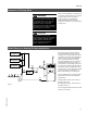

Connections
20
Venting Connection (continued)
Installing Z-FLEX pipe and fittings
J Use liberal beads of silicone to seal
joints.
J Use pipe hangers or metal strapping
to support vent pipe.
J Vent length should be as short and as
direct as possible.
J Clearance to combustibles must be
maintained at 3”. Fiberglass insulation
sleeve material may be installed over
pipe to reduce clearance to 1” from
combustibles. Tape sharp edge of pipe
to allow ins ulation to slide over.
Remove tape when finished. Do not
enclose vent in combustible material.
J Do not install vent pipe in joist space
closed in by drywall or other ceiling
materials which prevent accessibility.
J Do not install vent pipe in an unheated
space where freezing temperatures
occur.
J Do not use screws to secure the vent
pipe except at the boiler fan adaptor
connection (see Fig. 7).
Use a hacksaw or sheet metal s nips to
cut the pipe to size. Use a file to
smooth rough edges. Pipe must be
round and not bent into an oval shape.
All joints must be made with high
temperature silicone.
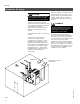
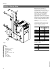
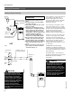
The connection to the boiler is made
with a short length (e.g. 8½”) of pipe
(male end on each s ide). Apply a bead
of s ilicone to the fan adaptor and screw
the short length of pipe to the fan
adaptor with the #8 self-drilling
stainless screws provided (see Fig. 7).
Continue on from the short piece with
the rest of the venting. Do not install
vent pipe such that flue gases flow
downwards. There must be NO leakage
of flue gas into the space. Check for
leaks with gas t urned off and fan
running. Use a soapy solution to check
for vent leaks.
FLEXMASTER has drain fittings
available for condensate drainage from
the vent system. Experience has shown
not enough condensate forms to keep a
drain tap primed.
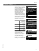
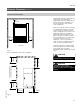
Use figures (Figs.7 - 8) to install the
venting system together with the Z-Flex
Model SVE, Series II Installation
Instructions.
5167 450 v1.4
C
F
45°
High temp.
silicone
Slide clamp
over screws
#8 stainless steel
self drilling screws
Fan outlet
Remove top panel
to access locking
band tightening
screw
Fig. 7
C
F
Support every 2’
with pipe hangers
Termination
box
Snow
line
Wall t himble
Slope up ¼”
per foot
Fig. 8
Under certain climatic conditions,
some building materials may be
affected by flue products expelled in
close proximity to unprotected
surfaces. Sealing or shielding of the
exposed surfaces with a corrosion
resistant material (e.g. aluminum
sheeting) may be required to prevent
staining or deterioration. The
protective material s hould be
attached and sealed (if necess ary) to
the building before a t t aching the vent
termination.
CAUTION
IMPORTANT
Annual inspection of the vent system,
fan and wheel for corrosion, leaks
and damage must be done by a
qualified technician to ensure safe
operation. Failure to perform periodic
inspections and repair or replacement
can cause property damage, s evere
personal injury, or los s of life.
Birdscreen must be intact at all t imes
to prevent dangerous blockage of
vent gases by birds’ nests.
WARNING