
Troubleshooting guide
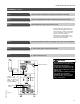


Additional Information
48
Parts List
Parts
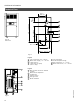
001 Left panel
002 Right panel
003 Back panel
004 Top panel
005 Front access panel
006 Front upper panel
007 Mid panel
008 Control panel
009 Collector box
010 Collector box
brackets
011 Baffle plate (ECV-180, -200)
012 Collector box
lower cover
013 Fan inlet restrictor
plate (ECV-65 to 155)
014 Terminal strip cover
015 Pressure tube
bracket
016 Fan outlet restrictor
plate (ECV-65, -80)
017 Venter gasket
018 Magnetek blower
019 Pressure switch
020 Thermowell
021 Thermowell nipple
022 Assembled cast-iron
heat exchanger
023 Section - right side*
024 Section - lef t side*
025 Section - intermediate*
026 Section - intermediate with pilot
openingonright*
027 Section - intermediate with pilot
openingonleft*
028 Manifold
029 Pipe plug
1
/
8
“
030 Manifold orifices
Natural gas
0-2000 ft.
2000-4500 ft.
4500-7000 ft.
LP
0-2000 ft.
2000-4500 ft.
4500-7000 ft.
031 Stainless steel
burner tube
032 Burner mounting
saddle
033 Burner tube for pilot
mounting
034 Pilot igniter assembly w/ shield
Q3451A2012
035 Ignition control
module S8600M
037 Gas valve
VR8204M
039 Pilot orifice
NG .020”
LP .014”
040 Pilot bracket for
Q3451A2012
041 Pilot shield
042 Manual reset
safety high limit
control (248°F)
043 Adjustable aquastat
044 Thermometer
045 Pump aquastat
046 Support bracket
upper
lower
047 Insulation cover
left side
right side
048 Insulation plate
left side
right side
049 Hex bushing, 1½” x 1¼“
050 Pressure relief valve, ¾”
30 psig
Watts M335
051 Pressure gauge
0-100 psig
052 Flame roll-out switch
60T15 L (200°F)
053 Sequence timer
14S22
054 Transformer
120/24V 40VA
055 Switching relay
056 Terminal strip
057 Flame roll-out switch
60T15 235F (235°F)
* When ordering replacement boiler
sections, order 4 push nipples per
intermediate section and 2 push
nipples per side section.
5167 450 v1.45167 450 v1.4