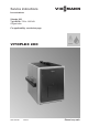
Service instructions VIESMANN for contractors Vitoplex 200 Type SX2A, 700 to 1950 kW Oil/gas boiler For applicability, see the last page VITOPLEX 200 5692 849 GB 10/2013 Please keep safe.
Safety instructions Safety instructions Please follow these safety instructions closely to prevent accidents and material losses. Safety instructions explained Note Details identified by the word "Note" contain additional information.
Safety instructions Safety instructions (cont.) If you smell flue gas Danger The simultaneous operation of the boiler and appliances that extract air to the outside can result in life threatening poisoning due to reverse flow of the flue gas. Fit an interlock circuit or take suitable steps to ensure a sufficient supply of combustion air. Danger Flue gas can lead to life threatening poisoning. ■ Shut down the heating system. ■ Ventilate the installation site. ■ Close all doors in the living space.
Safety instructions Safety instructions (cont.) Repair work ! Please note Repairing components that fulfil a safety function can compromise the safe operation of the system. Faulty components must be replaced with original Viessmann spare parts. Auxiliary components, spare and wearing parts Please note Spare and wearing parts that have not been tested together with the system can compromise its function.
Index Index Product information Intended use......................................................................................................... 6 Commissioning, inspection, maintenance Steps - commissioning, inspection and maintenance.......................................... Further details regarding the individual steps....................................................... 7 9 Parts lists Parts list................................................................................................
Product information Intended use The appliance is only intended to be installed and operated in sealed unvented heating systems that comply with EN 12828, with due attention paid to the associated installation, service and operating instructions as well as the details in the datasheet. It is only designed for the heating up of heating water. Commercial or industrial usage for a purpose other than the heating up of heating water shall be deemed inappropriate.
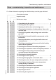
Commissioning, inspection, maintenance Steps - commissioning, inspection and maintenance For further information regarding the individual steps, see the page indicated Commissioning steps Inspection steps Maintenance steps • • • • • • • • 1. Commissioning the system........................................... 9 2. Shutting down the system............................................. 10 3. Opening the boiler door and cleaning cover............... 11 4.
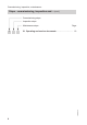
Commissioning, inspection, maintenance Steps - commissioning, inspection and… (cont.) Commissioning steps Inspection steps Maintenance steps 21. Operating and service documents................................
Commissioning, inspection, maintenance Further details regarding the individual steps Commissioning the system Operating and service instructions for the control unit and the burner 01. Close the gas shut-off valve and open the boiler door. 02. Check the seating of turbulators C in hot gas flues B. Turbulator spring clips D must lock into place behind first constriction E. 05. Enter the amount of fill water and water hardness into the table in chapter "Checking the water quality".
Commissioning, inspection, maintenance Further details regarding the individual steps (cont.) 12. The dew point range must be cleared as quickly as possible. For this reason prevent all heat supply to consumers when heating the system from cold. This also applies when restarting after maintenance and cleaning work. ! Please note During boiler heat-up, unpleasant fumes and odours can result from outgassing from the thermal insulation, the thermal block and the paint. Vent the room during commissioning.
Commissioning, inspection, maintenance Further details regarding the individual steps (cont.) Opening the boiler door and cleaning cover Note On gas burners, disconnect the gas supply pipe.
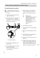
Commissioning, inspection, maintenance Further details regarding the individual steps (cont.) Cleaning the turbulators, heating surface, flue outlet and flue pipe 1. Pull turbulators B out towards the front with a quick tug. For this, use turbulator extractor A from the cleaning equipment. 3. Remove combustion residues from the flue pipe and the flue outlet through the cleaning aperture in flue outlet E using a vacuum cleaner. 5692 849 GB 2. Clean flues C and combustion chamber D with the brush.
Commissioning, inspection, maintenance Further details regarding the individual steps (cont.) Inserting turbulators, securing the boiler door and cleaning cover Note On gas burners, mount the gas supply pipe. Check all gas connections for tightness. Danger Escaping gas leads to a risk of explosion.
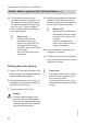
Commissioning, inspection, maintenance Further details regarding the individual steps (cont.) 1. Push turbulators C far into hot gas flues B. Spring clip E must snap into place behind first constriction D. 2. Tighten screws A crosswise (torque 25 Nm). Danger Leaks can lead to risk of poisoning through escaping gas. Check gaskets carefully. Note This snapping into place prevents the turbulators from slipping forward during boiler operation.
Commissioning, inspection, maintenance Further details regarding the individual steps (cont.) Pump controlled pressure maintaining systems In heating systems with automatic pressure maintaining systems provide individual protection by installing an expansion vessel for each boiler. This applies in particular to pump-controlled systems with integral deaeration. Boiler output Expansion vessel kW l up to 1000 140 up to 2100 300 It reduces the frequency and level of pressure fluctuations.
Commissioning, inspection, maintenance Further details regarding the individual steps (cont.) Enter the amount of top-up water and the total hardness of the feed and boiler water into the table. Meter reading Fill and top- Total water up water volume m3 m3 Total hardness Feedwater Boiler water pH value Date m3 The pH value should be between 9 and 10.5. 5692 849 GB The total hardness of the feed and topup water must not exceed 0.11 °dH (total value of alkaline earths ≤ 0.02 mol/m3).
Commissioning, inspection, maintenance Further details regarding the individual steps (cont.) Cleaning the sight glass in the boiler door Note Check the gaskets and hose connection for leaks. Checking the mixer for ease of operation and leaks 1. Remove the motorised lever from the mixer handle. 2. Check the mixer for ease of operation. 3. Check the mixer for leaks. Replace the O-ring gaskets if the mixer is leaking. 4. Snap the motorised lever into place.
Commissioning, inspection, maintenance Further details regarding the individual steps (cont.) Rated heating output kW 1600 1950 Pressure drop on the hot gas side Pa 650 850 mbar 6.5 8.5 To protect the system against dew point corrosion, burner stage 2 (full heating output) must be set to the rated boiler heating output. It must remain switched on, also during the summer months (burner stage 2 on constant standby).
Commissioning, inspection, maintenance Further details regarding the individual steps (cont.) Operating and service documents 1. Complete and detach the customer registration card: ■ Hand the system user their section for safekeeping. ■ Retain the heating contractor's section. 5692 849 GB 2. File all parts lists, operating and service instructions in the folder and hand this over to the system user. The installation instructions are no longer required after the appliance has been installed.
Parts lists Parts list Parts 001 Boiler door 002 Studs 003 Sight glass pack, comprising pos.
Parts lists Parts list (cont.
Parts lists Parts list (cont.
Parts lists Parts list (cont.
Parts lists Parts list (cont.
Parts lists Parts list (cont.
Parts lists Parts list (cont.
Water quality Water quality requirements Note Observing the following requirements is necessary to safeguard your warranty rights. The warranty excludes damage due to corrosion and scaling. Heating systems with rated operating temperatures up to 100 °C (VDI 2035) Water used in heating systems must meet the chemical levels of the Drinking Water Ordinance [Germany]. If well water or similar is used, it should be tested for suitability before filling the system.
Water quality Water quality requirements (cont.) When engineering the system, observe the following: ■ Install shut-off valves in the different sections. This prevents the need for draining all the heating water in the case of repairs or system expansion. ■ Install a water meter to record the amount of the fill and top-up water. Enter the volume of fill water and the water hardness into the boiler service instructions.
Water quality Water quality requirements (cont.) The characteristic blackening of the water after some time in use indicates that free oxygen is no longer present. The technical rules and in particular VDI Directive 2035-2 therefore recommend that heating systems are designed and operated so that a constant ingress of oxygen into the heating water is prevented.
Water quality Using antifreeze in boilers When doing so, observe the following: ■ In general, follow the specifications given by the antifreeze manufacturer. ■ The properties of antifreeze and water are very different. ■ The temperature stability of the antifreeze must be sufficient for the particular application. ■ Check the compatibility with sealing materials. If other sealing materials are used, take this into account when designing the system.
Water quality Using antifreeze in boilers (cont.) 5692 849 GB ■ After filling, ensure there are no more air cushions in the system. When the temperature falls, gas cushions form negative pressure and this can draw air into the system. ■ After initial filling and commissioning, but after 14 days at the latest, clean the integral dirt trap so the heat transfer medium can flow freely.
Commissioning/service reports Commissioning/service reports Commissioning Service Service Service Service Service Service Service Service Service Service Service Service Service Service date: by: date: by: date: by: date: by: date: 5692 849 GB by: 32
Specification Specification 5692 849 GB Rated heating output Flue gas parameters*4 Temperature at boiler water temperature 60 °C – at rated heating output – at partial load (60 %) Temperature at boiler water temperature 80 °C Product ID Efficiency η at ■ 100 % of the rated heating output (80/60 °C) ■ 30 % of the rated heating output (65/55 °C) *4 kW 700 900 1100 1300 1600 1950 °C °C °C 180 125 195 CE-0085BQ0020 % 92.2 92.2 92.2 92.3 92.2 92.3 % 96.4 96.5 96.6 96.6 96.5 96.
Certificates Declaration of conformity We, Viessmann Werke GmbH&Co KG, D-35107 Allendorf, declare as sole responsible body, that the following product complies with the standards specified: Vitoplex 200, type SX2A, 700 to 1950 kW with the Vitotronic boiler control unit EN 267 EN 303 EN 676 EN 14394 EN 50090-2-2 EN 55014-1 EN 55014-2 EN 60335-1 EN 60335-2-102 EN 61000-3-2 EN 61000-3-3 EN 62233 TRD 702 In accordance with the following Directives, this product is designated with _-0085: 2004/108/EC 2006/42/
Certificates Manufacturer's certificate according to the 1st BImSchV [Germany] We, Viessmann Werke GmbH&Co KG, D-35107 Allendorf, confirm that the product Vitoplex 200, type SX2A, 700 to 1950 kW complies with the following conditions stipulated by the 1st German Immissions Order (BImSchV): ■ NOx limits in accordance with paragraph 6 (1). ■ Flue gas loss of max. 9 % in accordance with paragraph 10 (1). ■ Standard seasonal efficiency [to DIN] of at least 94 % in accordance with paragraph 6 (2).
Keyword index Keyword index A Adjusting the burner...........................17 Anti-corrosion measures....................29 B Boiler door – Opening..........................................11 – Securing.........................................13 Boiler water total hardness................16 C Checking the expansion vessel.........14 Checking the function of the safety equipment..........................................14 Checking the system pressure...........14 Checking the water quality................
5692 849 GB
5692 849 GB
5692 849 GB
7438486 7438490 Viessmann Werke GmbH&Co KG D-35107 Allendorf Telephone: +49 6452 70-0 Fax: +49 6452 70-2780 www.viessmann.com 40 7438487 7438488 Viessmann Limited Hortonwood 30, Telford Shropshire, TF1 7YP, GB Telephone: +44 1952 675000 Fax: +44 1952 675040 E-mail: info-uk@viessmann.com Subject to technical modifications. Serial No.