
Technical Manual
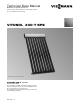

Vitosol 200-T, SPE Technical Data
5693 556 v1.0
66
Installation on Flat Roofs
Design Information
When installing collectors, maintain the minimum
clearances towards the roof edge in accordance with
DIN 1055.
If the roof size necessitates a split array, ensure that
sections of the same size are created. The collectors can
be secured on any solid substructure or on concrete slabs.
When installing collectors on concrete slabs, secure them
with additional ballast against slippage, tipping and lifting.
Slippage is the movement of the collectors on the roof
surface due to wind, because of insufficient friction
between the roof surface and the collector fixing system.
Collectors can be secured by guy ropes or by being fixed
to other roof structures.
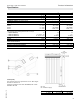
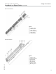
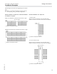
Legend
A Footplates
B Rear support
C Collector support
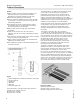
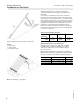
Collector supports with fixed angle of inclination
Angle of
inclination
30° 45° 60°
a in.
(mm)
95
(2413)
86.6
(2200)
72.36
(1838)
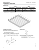
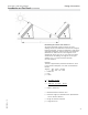
Vertical tube installation (elevated)
Combination x in. (mm) y in. (mm)
1.63 m
2
/1.63 m
2
23.6/23.6 (600/600) 25.4 (644)
1.63 m
2
/3.26 m
2
23.6/47.2 (600/1200) 37.4 (949)
3.26 m
2
/3.26 m
2
47.2/47.2 (1200/1200) 48.6 (1234)
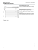
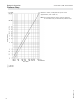
Ballast and max. load on the substructure
Calculation in accordance with DIN 1055-4, 3/2005
and DIN 1055-5, 7/2005 or applicable local codes.
Two support slabs each, both A and B are required
for every collector.
Ballast weight requirements, as well as the calculation of
additional live loads (due to installation of solar collectors),
must be evaluated by a professional structural engineer.
Note: For calculating z, see page 7.