Please file in Service Binder Installation Instructions for use by heating contractor Vitosol-F Models SV, SH Flat plate solar collectors for sloped roofs, flat roofs and freestanding installation VITOSOL-F Vitosol 100-F Model SV1 Vitosol 100-F Model SH1 Vitosol 200-F Model SV2 Vitosol 200-F Model SH2 IMPORTANT Read and save these instructions for future reference. 5285 710 v2.
Safety, Installation and Warranty Requirements Safety, Installation and Warranty Requirements Please ensure that these instructions are read and understood before commencing installation. Failure to comply with the instructions listed below and details printed in this manual can cause product/property damage, severe personal injury, and/or loss of life. Ensure all requirements below are understood and fulfilled (including detailed information found in manual subsections).
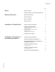
Contents Page Safety General Information .................................................................. 2 Important Regulatory and Installation Requirements . . . . . 5 About these Instructions ....................................................... 6 ................................................................ 6 ............................................................... 7 ....................................................................
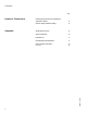
Contents Page Hydronic Connections Installing the Connection Set and Collector Temperature Sensor . . . . . . . . . . . . . . . . . . . . . . . . . . . . . . . . . . . . . . . . . . . . . . . . . . . . . . . . . . . . . . . . 24 Collector Supply and Return Piping Appendix .................................... 25 Sample System Layout . . . . . . . . . . . . . . . . . . . . . . . . . . . . . . . . . . . . . . . . . . . . . . . . . . . . . . . . . . . 25 System Installation . . . . . . . . . . . . . . .
Safety Important Regulatory and Installation Requirements Codes The installation of solar heating systems might be governed by individual local rules and regulations for this type of product, which must be observed. The installation of this unit shall be in accordance with local codes. Always use latest editions of codes. Mechanical room Ensure the mechanical room complies with the requirements of the system design guideline and/or technical data manual.
General Information About these Instructions Take note of all symbols and notations intended to draw attention to potential hazards or important product information. These include ”WARNING”, ”CAUTION”, and ”IMPORTANT”. See below. WARNING Indicates an imminently hazardous situation which, if not avoided, could result in substantial product/property damage, serious injury or loss of life.
General Information Notes on Installation H The entire solar heating system H Although the glass collectors surfaces H Employ suitable safety measures to H The collectors should, as far as H The collectors must be securely H The collectors should be mounted should be installed in accordance with the accepted rules of technology, observing all relevant accident prevention regulations. prevent falls, falling objects and roof damage due to insufficient load bearing capacity, e.g.
Installation on Sloped Roofs Overview of System Components Sloped roof mounting hardware Roof bracket Clamping bracket Joining element for mounting rail Mounting rail, 46¼” / 1175 mm or 91¾” / 2330 mm Washer, Ø ¼” / 8.4 mm Hexagon screw, M 8 x 10 Mounting plate Clamping bracket Locking bolt w/ threaded stud Hexagon nut Zinc plated countersunk screws, 3.
Installation on Sloped Roofs Installing the Mounting Frames Install the panel array level or slightly inclined (approximately ½” / 10 mm) towards the connection side to ensure complete venting. Always locate an air vent at the highest point in the piping. Attaching roof brackets on shingled roof 1. The roof brackets should be laid out as close as possible to the dimensions shown in the chart on page 10 for SV collectors, and page 11 for SH collectors. 2.
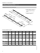
Installation on Sloped Roofs Installing the Mounting Frames (continued) Installation dimensions for ten SV collector panels 6. Re-apply shingles, if required, and ensure all roof penetrations are thoroughly sealed with silicone sealant. 36¼” / 923 mm 16” / 154 mm 7. Continue with mounting rail installation on page 12. 36¼” / 923 mm 36¼” / 923 mm 75” - 82½” 1900 - 2100 mm Dimensions for Model SV collectors 1 2 3 4 5 6 8 10 Dim.
Installation on Sloped Roofs Installing the Mounting Frames (continued) Installation dimensions for ten SH collector panels 8. Follow steps 1 through 7 from the previous pages. 86½” / 2200 mm 7¾” / 201 mm Dimensions for Model SV collectors Number 1 2 3 4 5 6 8 10 7266 286¼ 9688 381½ 12110 476¾ 14532 572 19376 763 24220 953½ Dim. A mm inches 2422 95¼ 4844 191 Dim. B mm inches 2250 88½ 4500 177 D+D Dim. C*1 mm inches 86 3½ 172 6¾ 182.
Installation on Sloped Roofs Installing the Mounting Frames (continued) Installing the mounting rails IMPORTANT 1. Turn the T-slot bolts 90° for all installation steps. 1. Secure the joining elements . the mounting rails into IMPORTANT 2. Make sure the mounting rail profile is as shown. Failure to install the mounting rail correctly will not allow proper mounting plate connection. 2. Secure the mounting rails to the roof must be bracket. The locking bolt turned 90°. IMPORTANT 3.
Installation on Sloped Roofs Installing the Solar Collectors CAUTION 3. Do not stand on the collectors. 1. IMPORTANT Interconnecting pipes must be free from damage and contamination. Lubricate all plug-in joints (O-ring seals) on the collectors. Use only the special grease supplied with the connection set. IMPORTANT On the first and last collector, the side to which the rating plate is attached must be on the outside. Ensure that dimension “r” is maintained for first and last collector. 3. 2. 1.
Installation on Sloped Roofs Installing the Solar Collectors (continued) 7. Tighten all clamping brackets. (part of the 8. Press the cover caps connection set) into the mounting rails. 9. Remove all labels. CAUTION Arrows on the first and last collector in a series must point towards the outside. CAUTION 5285 710 v2.0 Viessmann strongly recommends not removing the cover foil from the collectors until after initial start-up in order to prevent overheating.
Installation on Flat Roofs or Freestanding Installation Overview of System Components Legend: b Collector support Cross brace Adjustable support, lower part Adjustable support, upper part (two part) Washer, Ø 0.33” / 8.4 mm Hexagon nut, M8 Hexagon screw, M8 x 20 Support rail (only for flat roofs with gravel filling) Retaining plate Clamping bracket Connecting brace Connecting ties 4” / 100 mm a Ø 0.43” / 11 mm 3” / 75 mm 2” / 50 mm 3¼” / 80 mm a b SV inches mm 63.8 1620 70.
Installation on Flat Roofs or Freestanding Installation Determining the Collector Row Distance “z” IMPORTANT When installing several collectors in series, maintain a distance of “z”. h h z z = h Legend: z=Collector row distance h=Collector height α=Collector angle of inclination β=Solar angle Example: Model SV Toronto is located at approx. 43° latitude. 1. Determine the angle of the sun β.
Installation on Flat Roofs or Freestanding Installation Installing the Collector Supports and Adjustment of the Angle of Inclination 1. Secure the lower adjustable support with the cross brace. 2. Secure the upper and lower adjustable supports in accordance with the required angle of inclination. 2. 5285 710 v2.0 1.
Installation on Flat Roofs or Freestanding Installation Installing Freestanding Installation (on substructures) 5. 6. 8,5 1. Mount the understructure (to be provided on site), e.g. U-channels, at right angles to and level with the installation orientation of the collectors according to the dimensions shown in the drawing. 2.
Installation on Flat Roofs or Freestanding Installation Installing Freestanding Installation (on substructures) 7. Position the first collector into the retaining plates and push right up to the spacer lip of the connecting brace. 11. 10. IMPORTANT Install the collector panel so that the rating plate side of the first and last collector is on the outside (note sticker)! If only one collector is to be installed, connect the piping opposite the nameplate side. 9. 7. 8.
Installation on Flat Roofs or Freestanding Installation Installing a Freestanding Installation (with weight inserts) 1. Observe the max. load and distance from the edge of the roof for on-site substructure. CAUTION A structural engineer must be consulted to ensure that the existing roof structure is capable of carrying the additional weight of the collectors, insert weights and support slabs. 2. Remove any gravel etc.
Installation on Flat Roofs or Freestanding Installation Installing Freestanding Installation (with weight inserts) 6. Secure the support rails between the cross braces. Note: With an angle of inclination of 25 and 30°, the front support rails can be secured in the center. 7. Apply weights (see tables on page 23). 8. Secure two connecting ties diagonally side by side to the adjustable supports (for up to six collectors). 9.
Installation on Flat Roofs or Freestanding Installation Installing Freestanding Installation (with weight inserts) 9. Position the first collector into the retaining plates and push right up to the spacer lip of the connecting brace. Center the distance when fitting only a single collector. 13. 12. IMPORTANT 11. 9.
Installation on Flat Roofs or Freestanding Installation Installing Freestanding Installation Secure against slipping*1 Model SV Installation height above ground level ft.
Hydronic Connections Installing the Connection Set and Collector Temperature Sensor 6. 1. 7. 1. 2. 4. 8. When assembling the locking ring compression fitting, observe the following: H All pipe ends must be square and deburred. H Push the union nut and the locking ring onto the pipe adaptor and lightly lubricate the threads with oil. H Push the pipe into the compression fitting as far as it will go. H Initially, turn the union nut by hand, then tighten with an open ended spanner by another ¾ turn.
Hydronic Connections / Appendix p Collector Supply and Return Piping H For the piping connecting the collectors to the Solar Divicon pumping station, Viessmann recommends the use of commercial copper pipe and bronze fittings, or non-galvanized steel pipe. PEX or other plastic pipes are not suitable for solar collector supply and return piping. H Use only high temperature solder or brazing material when connecting the copper pipes in the collector piping.
Appendix System Installation Please refer to the Vitosol ”System Design Guidelines” for supplementary notes on installation examples and system types. H The connecting lines must be pressure and temperature-resistant (observe the max. shutdown temperature of the collector). H To guarantee the satisfactory operation of the solar heating system, install the pipes so that complete air venting is assured. CAUTION Use only red bronze fittings, brass fittings and copper piping.
Appendix Initial Start-up The collector circuit must be protected in such a way that at the highest possible collector temperature (shutdown temperature) no heat transfer fluid can escape from the safety valve, or the air vent. This is achieved by the appropriate sizing of the expansion tank and matching of the system pressure. IMPORTANT Under cold fill conditions, a minimum static pressure must be maintained. It can be calculated by the following: 22 psig +0.45 psig x_____h(ft.) or 1.5 bar + 0.
Appendix Post-Installation j Has the solar circuit been installed in accordance with the circuit diagram and all relevant standards? j Have the collectors been installed with a slight upward gradient towards the piping side? j Have the supply and return connections been carried out and pressure tested? Printed on environmentally friendly (recycled and recyclable) paper.