Operating instructions VIESMANN for the system user Heating system with control unit for constant operation Vitotronic 100, type GC1B or GC4B VITOTRONIC 100 5592 669 GB 2/2011 Please keep safe.
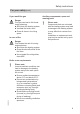
Safety instructions For your safety Please follow these safety instructions closely to prevent accidents and material losses. Safety instructions explained Danger This symbol warns against the risk of injury. ! Please note This symbol warns against the risk of material losses and environmental pollution. Note Details identified by the word "Note" contain additional information. Target group These operating instructions are for the heating system user.
Safety instructions For your safety (cont.) If you smell flue gas Danger Flue gas can lead to life-threatening poisoning. ■ Shut down the heating system. ■ Ventilate the boiler room. ■ Close all doors in the living space. In case of fire Ancillary components, spare and wearing parts ! Please note Components that are not tested with the heating system may lead to damage to the heating system, or may affect their various functions.
Index Index Introductory information Commissioning..................................................................................................... Your system is preset at the factory..................................................................... Special considerations for multi boiler systems.................................................... Terminology.......................................................................................................... 6 6 7 7 Operation Controls........
Index Index (cont.) Rooms are too hot................................................................................................ There is no hot water............................................................................................ The DHW is too hot.............................................................................................. "ã" flashes on the display .................................................................................. "ë" flashes on the display...............
Introductory information Commissioning The commissioning and matching of the control unit to local conditions and building characteristics, as well as instructing the user in the operation of the system, must be carried out by your heating contractor. As the user of new combustion equipment, you may be obliged to notify your local flue gas inspector of the installation [check local regulations].
Introductory information Special considerations for multi boiler systems The Vitotronic 100 can be used in the following systems: ■ Single boiler systems ■ Multi boiler systems with a Viessmann cascade control unit ■ Multi boiler systems of a higher third party control unit In multi boiler systems (systems with several boilers), each boiler is equipped with its own control unit. These control units are regulated by the higher control unit. Make the required settings (e.g.
Operation Controls Opening the control unit The programming unit is located behind the cover flap. Brief operating instructions can be found on the back of the cover flap. To open, pull the flap from the top edge forward. A A Cover flap Programming unit °C 48 s A OK Confirms your selection or saves the setting. No function. Enables you to call up the menu for settings and scanning. 5592 669 GB Takes you to the previous step in the menu or cancels a setting that has been started.
Operation How to use the controls Press . This takes you to the menu for settings and scanning. Standard display °C 48 Symbols on the display These symbols are not always displayed, but appear subject to the system version and the operating state. Flashing displays indicate that modifications can be made.
Start-up/shutdown Starting the heating system Controls with open hinged cover flap For cover flap, see page 8.
Start-up/shutdown Starting the heating system (cont.) Type GC4B C D °C 48 s A BA E A ON indicator (green) B Fault indicator (red) C Emissions test switch (only for service purposes) F ON/OFF switch H Fuses Ask your heating contractor about the following: ■ Boiler and relevant control unit type ■ Level of the required system pressure ■ Position of the pressure gauge, shutoff valves, gas shut-off valve, ventilation apertures 3. Switch ON the power supply, e.g.
Start-up/shutdown Shutting down the heating system With frost protection monitoring Select the heating program " " for standby mode (frost protection monitoring). Press the following keys: 1. for settings; " 5. OK to confirm. ■ No central heating. ■ No DHW heating. ■ Frost protection for the boiler and the DHW cylinder is enabled. " flashes. 2. OK to confirm; " " flashes. 3. OK to confirm; the currently selected heating program flashes.
Central heating Selecting the set boiler water temperature Select a sufficiently high set boiler water temperature (heating flow temperature) so that the required room temperature can be achieved. Factory setting: 75 °C 4. OK to confirm; the selected temperature value flashes. Press the following keys: 5. / 1. for settings; " 3. for set boiler water temperature; " " flashes. for the required set boiler water temperature. " flashes. 2. OK to confirm; " " flashes. 6.
DHW heating Required settings (DHW heating) If you want DHW heating, check the following points: ■ Have you set the required DHW temperature? For settings, see the next chapter. ■ Have you set the correct heating program? For settings, see page 14. Setting the DHW temperature Factory setting: 50 °C 3. OK to confirm; temperature value flashes. Press the following keys: 4. / 1. for settings; " 2. until " " flashes. for required DHW temperature. " flashes. 5.
DHW heating Stopping DHW heating You do not want DHW, but do want to heat the rooms. Press the following keys: 1. for settings; " 5. OK to confirm; DHW heating and central heating are stopped, frost protection monitoring is activated (standby mode). " flashes. 2. OK to confirm; " " flashes. 3. OK to confirm; the currently selected heating program flashes. 4. / until " " flashes. 5. OK to confirm. 6. for settings; " " flashes. 7. until " " flashes. 8. OK to confirm; temperature value flashes.
Further adjustments Setting the temperature unit (°C/°F) Factory setting: °C 3. OK to confirm; " " flashes. Press the following keys: 4. / 1. for settings; " 2. until " " flashes. for required temperature unit ("°C" or "°F"). " flashes. 5. OK to confirm; the new temperature unit is saved. Restoring factory settings You can simultaneously reset all changed values to the factory settings. Press the following keys: 1. for settings; " " flashes. 2. until " " flashes. 3.
Scanning Scanning information Subject to the connected components and settings made, you can scan current temperatures and operating conditions. Press the following keys: 1. for settings; " 2. until " " flashes. 6. OK to confirm; the value is reset. Example: The number "3" is displayed, indicating the current boiler water temperature. ¸ " flashes. 3 °C 65 3. OK to confirm. 4. / for the required information. 5.
Scanning Scanning information (cont.) 50 Explanation °C Temperature sensor / 54 50 °C Temperature sensor aÖ 5 70 °C Collector temperature 6 55 °C Temperature sensor aJA 7 55 °C Temperature sensor aJB 2 6 3 5 7 2 h Hours run burner single stage, stage 1 or modu1 lating 2 6 3 5 7 2 h Hours run burner stage 2 2 0 1 3.
Scanning Scanning information (cont.) Display 002850 9 Explanation Solar yield in kWh Notes Displayed only if a Viessmann solar control module is installed. The value can be reset to "0" with "D". Scanning the service messages If your heating system is due for a service, the symbol flashes on the display, and the following displays appear. Your heating contractor can select when a service should be carried out: After a certain number of burner hours run, e.g. 2500 hours.
Scanning Scanning fault messages If any faults have occurred in your heating system, the symbol flashes on the display and the fault code is shown. The red fault indicator also flashes (see page 10). Calling up an acknowledged fault message Press OK for approx. 4 s. Note If there are several fault messages, you can scan these in sequence by pressing / . Example: Fault code shown: "50" ã 1 50 1. Notify your heating contractor of the fault code.
Emissions test mode Emissions test mode Emissions test mode for testing flue gas with boiler water temperature raised briefly. This test mode should only be activated by your flue gas inspector during the annual inspection. Switch the emissions test switch (see page 10 and 11) to . The display will then show the following: °C 48 The following functions are activated: ■ The burner is switched ON (the display shows symbol ). Note Burner start-up can be delayed, e.g. through fuel oil preheating.
What to do if... Rooms are too cold Cause The heating system is off. Control unit incorrectly adjusted. Only when operating with DHW heating: DHW priority is enabled (" " is displayed). No fuel. symbol is shown on the display. For LPG/oil: Check the fuel reserves and re-order if required. With natural gas: Open the gas shut-off valve. If necessary, check with your gas supply utility. Scan the type of fault, make a note of the fault code and acknowledge the message (see page 20).
What to do if... Rooms are too cold (cont.) Cause Burner start faulty. The symbol is displayed and the red fault indicator on the burner is illuminated. Vitoair draught stabiliser faulty. Remedy Press the reset button on the burner hood or on the boiler front panel. If there is no reset button, switch the ON/OFF switch (see pages 10 and 11) first OFF and then ON again. Contact your local heating contractor if the burner still fails to start. Contact your local heating contractor.
What to do if... There is no hot water Cause The heating system is off. Control unit incorrectly adjusted. No fuel. The symbol is shown on the display. Remedy ■ Switch ON the ON/OFF switch (see pages 10 and 11). ■ Switch ON the mains isolator, if installed (outside the boiler room). ■ Reset the MCB in the power distribution board (main domestic MCB). Check settings and correct if required: ■ DHW heating must be enabled (see page 14). ■ Set DHW temperature (see page 14).
What to do if... "ã" flashes on the display Cause Heating system fault. Remedy Scan the type of fault, make a note of the fault code and acknowledge the message (see page 20). If necessary, notify your heating contractor. "ë" flashes on the display Remedy Notify your local heating contractor and acknowledge the service message with OK (see page 19). 5592 669 GB Cause The time for a service, as specified by your heating contractor, has arrived.
Maintenance Maintenance Cleaning All equipment can be cleaned with a commercially available domestic cleaning agent (non-scouring). Clean the surface of the programming unit with a microfibre cloth. Inspection and maintenance Inspection and maintenance of your heating system is prescribed by the Energy Savings Order and DIN 4755, DVGW-TRGI 2008 and DIN 1988-8. Regular maintenance ensures troublefree, energy efficient, environmentally responsible and safe heating.
Maintenance Maintenance (cont.) Potable water filter (if installed) 5592 669 GB To maintain high hygienic standards, proceed as follows: ■ Replace filter element on non-back flushing filters every six months (visual inspection every two months). ■ On back flushing filters, back flush every two months.
Terminology Constant temperature operation Heating circuit In constant temperature operation, the heating water is constantly heated to the selected boiler water temperature. A heating circuit is a sealed circuit between the boiler and radiators, in which the heating water circulates. Heating program Heating circuit pump The heating program determines whether you heat your rooms and DHW, or only heat DHW, or whether you shut down your heating system with frost protection monitoring.
Terminology (cont.) Summer mode Heating program " ". At warmer times of the year, i.e. when the rooms do not have to be heated, you can stop heating mode. The boiler remains enabled for DHW heating. Cylinder primary pump Circulation pump for heating the DHW in the DHW cylinder. Drinking water filter 5592 669 GB A device that removes solids from the water. The drinking water filter is installed in the cold water pipe upstream of the DHW cylinder or the instantaneous water heater.
Keyword index Keyword index A Actual temperature.............................28 Frost protection....................................6 Frost protection monitoring....12, 13, 15 B Balanced flue operation.....................28 Boiler water temperature....................28 H Heating and DHW................................6 Heating circuit....................................28 Heating circuit pump..........................28 Heating mode ■ Setting............................................
Keyword index Keyword index (cont.) P Power failure........................................6 Pressure gauge..................................11 Programming unit.................................8 Pump ■ Cylinder..........................................29 ■ Heating circuit.................................28 R Reset..................................................16 Resetting data....................................17 Resetting fuel consumption................17 Resetting hours run...........................
Your contact Contact your local contractor if you have any questions regarding the maintenance and repair of your system. You may, for example, find local contractors on the internet under www.viessmann.com. Viessmann Werke GmbH&Co KG D-35107 Allendorf Telephone: +49 6452 70-0 Fax: +49 6452 70-2780 www.viessmann.com 32 Viessmann Limited Hortonwood 30, Telford Shropshire, TF1 7YP, GB Telephone: +44 1952 675000 Fax: +44 1952 675040 E-mail: info-uk@viessmann.