Installation and Service Instructions for use by heating contractor Vitotronic 300, Type GW5B Digital boiler control unit Vitotronic 300-K, Type MW1B Weather-compensated digital cascade control unit VITOTRONIC 300, GW5B VITOTRONIC 300-K, MW1B Vitotronic 300, GW5B Vitotronic 300-K, MW1B Product may not be exactly as shown IMPORTANT Certified as a component part for Viessmann boilers 5693 973 - 05 02/2015 Read and save these instructions for future reference.
General Vitotronic 300, GW5B and MW1B Installation and Service Safety, Installation and Warranty Requirements Please ensure that these instructions are read and understood before commencing installation. Failure to comply with the instructions listed below and details printed in this manual can cause product/property damage, severe personal injury, and/or loss of life. Ensure all requirements below are understood and fulfilled (including detailed information found in manual subsections).
Vitotronic 300, GW5B and MW1B Installation and Service Table of Contents Page 5693 973 - 05 General Safety, Installation and Warranty Requirements..............2 Product documentation......................................2 Warranty..........................................................2 Licensed professional heating contractor..............2 Advice to owner................................................2 Operating and Service Documentation..................2 Product Information......................
Table of Contents Vitotronic 300, GW5B and MW1B Installation and Service Power Supply Power Supply...........................................................38 Opening and Closing the Control Units Fitting the Control Unit Front......................................39 Opening the Control Unit...........................................39 Commissioning Testing the High Limit Safety Cut-out..........................40 Changing the Language on the Vitotronic 300-K...........
Vitotronic 300, GW5B and MW1B Installation and Service Table of Contents Page Code 1, Vitotronic 300, GW5B Calling up Coding Level 1..........................................71 Group 1 “General”....................................................71 Group 2 “ Boiler”......................................................72 Code 2, Vitotronic 300, GW5B Calling up Coding Level 2..........................................73 Group 1 “General”....................................................
Safety Vitotronic 300, GW5B & MW1B Installation and Service About these Instructions Take note of all symbols and notations intended to draw attention to potential hazards or important product information. These include “WARNING”, “CAUTION”, and “IMPORTANT”. See below. WARNING Warnings draw your attention to the presence of potential hazards or important product information.
Safety Vitotronic 300, GW5B & MW1B Installation and Service For your Safety CAUTION Follow these safety instructions closely to avoid the risk of injury and damage to property. H Operation Before operating the boiler, make sure you fully understand its method of operation. Your heating contractor should always perform the initial start-up and explain the system. Any warranty is null and void if these instructions are not followed. H Flue gas smell - Deactivate heating equipment. - Open windows and doors.
Preparing for Installation Vitotronic 300, GW5B and MW1B Installation and Service Designations in the System Example Overview of System Example Boiler Characteristics Page Vitocrossal, 200 CM2 Multi-boiler installation 9 H This system example is merely a generic layout and must therefore be checked on site for completeness and function. H Connect three-phase consumers via additional contactors. 8 5693 973 - 05 H With the Vitotronic 300-K, the communication module is integrated.
Vitotronic 300, GW5B & MW1B Installation and Service Preparing for Installation System Example Multi boiler system: Vitocrossal 200 CM2 Hydraulic installation layout 5693 973 - 05 Note: This layout is a basic example without shut-off devices or safety equipment. This does not replace the need for local engineering.
Preparing for Installation System Example 6 7 8 9 qP qQ qE qR qT qZ qU qI wP qO wQ qO wQ wW wR wE wT wE wT wZ wI wU wO 10 (continued) required Description Boiler I (cascade mode) Neutralizing system Boiler water temperature sensor KTS Supply temperature sensor, common heating supply VTS as contact temperature sensor (standard delivery for Vitotronic 300-K) or immersion temperature sensor Outside temperature sensor ATS Vitotronic 300-K Vitotronic 300, GW5B Boiler II (cascade mode) Neutralizing system
Vitotronic 300, GW5B & MW1B Installation and Service System Example Preparing for Installation (continued) Equipment required Pos.
Preparing for Installation System Example Vitotronic 300, GW5B & MW1B Installation and Service (continued) 12 5693 973 - 05 Electrical installation wiring
Vitotronic 300, GW5B & MW1B Installation and Service 5693 973 - 05 System Example Preparing for Installation (continued) 13
Preparing for Installation System Example Vitotronic 300, GW5B & MW1B Installation and Service (continued) Code required at every Vitotronic 300, GW5B 01:2 Group Function 2 “Boiler” Multi boiler system with cascade control via LON Boiler number at the Vitotronic: 07:2 2 “Boiler” Boiler 2 07:3 2 “Boiler” Boiler 3 07:4 2 “Boiler” Boiler 4 77:2 1 “General” Vitotronic 300-K with two Vitotronic 300, GW5B 77:3 1 “General” Boiler 3 77:4 1 “General” Boiler 4 LON participant number at the
Installation, Vitotronic 300, GW5B Vitotronic 300, GW5B & MW1B Installation and Service Overview of Electrical Connections Note: When connecting plugs aVD and aVH, bundle the individual cores of the cables close to the terminals. This prevents the cores from shifting into the neighboring voltage area.
Overview of Electrical Connections 16 Vitotronic 300, GW5B & MW1B Installation and Service (continued) 5693 973 - 05 Installation, Vitotronic 300, GW5B
Vitotronic 300, GW5B & MW1B Installation and Service Installation, Vitotronic 300, GW5B 120V External Connection Overview Legend A Pumps B To the control unit Pumps 120V Available pump connections sÖM1/A1 Switching contact sL Boiler pump 5693 973 - 05 Rated current: 2A~ * Maximum output 6FLA shared between all 120V outputs.
Installation, Vitotronic 300, GW5B Vitotronic 300, GW5B & MW1B Installation and Service Inserting Cables and Applying Strain Relief H Control unit fitted on the boiler: Route cables from below through the front panel of the boiler into the wiring chamber of the control unit. H Control unit fitted to the side of the boiler: Route cables from below out of the cable channel into the control unit. Legend A Cables with moulded strain relief B On-site cables; strip up to 4 in.
Installation, Vitotronic 300, GW5B Vitotronic 300, GW5B & MW1B Installation and Service Inserting the LON Communication Module Making the LON connection, see page 37.
Installation, Vitotronic 300, GW5B 120V External Connection Vitotronic 300, GW5B & MW1B Installation and Service (continued) 120V pumps with an amperage draw of >2FLA Contactor specification 120VAC 1A A Din rail B Contactor/relay (field supplied) C Pump D Power supply w/disconnect and protection 240V pumps Contactor specification 120VAC 1A A Din rail B Contactor/relay (field supplied) C Pump D Power supply w/disconnect and protection 208/460/575V 3 phase pumps 20 5693 973 - 05 Contactor specificati
Vitotronic 300, GW5B & MW1B Installation and Service Installation, Vitotronic 300, GW5B Connecting Actuators Legend A 24V Mixing Valve Adaptor B DIN Rail (in junction box) C 24V Valve Actuator D Valve Legend A 120V Mixing Valve Adaptor B DIN Rail (in connection enclosure) C 120V Valve Actuator D Valve 120V Valve Adaptor Rated voltage: Rated current: 1. Disconnect power to control. 120VAC max. 0.1 FLA 2. Install 120V or 24V valve adaptor on DIN rail inside connection enclosure. 3.
Installation, Vitotronic 300, GW5B Vitotronic 300, GW5B & MW1B Installation and Service Connecting the Central Fault Message Facility Rated voltage Rated current 120V~ max. 2A~ Connection of Low Water Cut-off Device 1. Remove jumper between terminals 12 and 15. 2. Make connection as shown in diagram. CAUTION The diagram shown is only a simplified conceptual drawing of a typical low water cut off (LWCO) device. Refer to the manual specific to the device for interconnection details.
Vitotronic 300, GW5B & MW1B Installation and Service Installation, Vitotronic 300, GW5B Connections to Safety Equipment 1. Connect the external safety equipment in series. Legend A DIN rail B Low water cutoff C Other safety controls Connections to Terminal aBA External shut-off 1. Remove jumper between terminals 19 and 20. 2. Connect dry contact. Controlled switch-off takes place when the contact is opened. WARNING 5693 973 - 05 The terminals should be used for safety switch-off purposes only (e.g.
Installation, Vitotronic 300, GW5B Vitotronic 300, GW5B & MW1B Installation and Service Blocking Boiler Externally/Adding to the Boiler Sequence Connection at plug aVD. Note: ‘Live’ contacts lead to short circuits or phase failure. The external connection must be floating. Contact A: H Contact closed: The boiler is removed from the boiler sequence. The isolation valve or the 3- way mixing valve are closed for constant return temperature control. Shunt pump or boiler circuit pump are switched off.
Vitotronic 300, GW5B & MW1B Installation and Service Installation, Vitotronic 300, GW5B Connecting the Burner The burner cables are included in the standard boiler delivery. Max. power consumption 3A.
Installation, Vitotronic 300-K Vitotronic 300, GW5B & MW1B Installation and Service Overview of Electrical Connections Note: When connecting plugs aVD, aVH, sA, sK, ? M2/M3 and sÖ M2/M3, bundle the individual wires of the cables close to the terminals. This ensures that, should there be an error, for example when detaching a wire, the wires cannot drift into the adjacent voltage area.
Vitotronic 300, GW5B & MW1B Installation and Service Installation, Vitotronic 300-K Overview of Electrical Connections, Vitotronic 300-K (continued) 5693 973 - 05 Legend A Vitotronic 300-K B Din rail 27
Installation, Vitotronic 300-K Vitotronic 300, GW5B & MW1B Installation and Service Mounting the Control Unit 1. Fasten metal backplate onto mounting surface with four fasteners. 2. Position midplate between backplate and connection enclosure. 3. Install midplate and connection enclosure onto backplate. 4. Fasten connection enclosure and midplate onto backplate with two fasteners. 5. Install control rear section onto connection enclosure housing. Hook control onto backplate tabs and pivot downwards.
Installation, Vitotronic 300-K Vitotronic 300, GW5B & MW1B Installation and Service Inserting Cables/Leads and Applying Strain Relief Run the cables from the connection enclosure into the control unit. Apply strain relief to cables. Cables with moulded strain relief clamp: Connect cable and strain relief clamp. OR Fasten cable to the cable lead with cable tie. 5693 973 - 05 Legend A Cables with moulded strain relief B On-site cables; strip up to 4 in. (100 mm) insulation.
Installation, Vitotronic 300-K Vitotronic 300, GW5B & MW1B Installation and Service Connecting Pumps * * Rated current: 2 A~ * Maximum pump output 6FLA shared between all 120V outputs.
Vitotronic 300, GW5B & MW1B Installation and Service Installation, Vitotronic 300-K Connecting Sensors Installation point for outside temperature sensor H North or north-western wall, 6.6 to 8.2 ft. (2 to 2.
Installation, Vitotronic 300-K Vitotronic 300, GW5B & MW1B Installation and Service 120V External Connection 120V pumps with an amperage draw of <2FLA A Din rail B Pump 120V pumps with an amperage draw of >2FLA Contactor specification 120VAC 1A A Din rail B Contactor/relay (field supplied) C Pump D Power supply w/disconnect and protection 240V pumps Contactor specification 120VAC 1A A Din rail B Contactor/relay (field supplied) C Pump D Power supply w/disconnect and protection 32 5693 973 - 05 208/46
Vitotronic 300, GW5B & MW1B Installation and Service Installation, Vitotronic 300-K Connecting Actuators Legend A 24V Mixing Valve Adaptor B DIN Rail (in junction box) C 24V Valve Actuator D Valve Legend A 120V Mixing Valve Adaptor B DIN Rail (in junction box) C 24V Valve Actuator D Valve 120V Valve Adaptor Rated voltage: 120 VAC Rated current: max. 0.1 FLA Recommended connection wire size: AWG 14 1. Disconnect power to control. 24V Valve Adaptor Rated voltage: 24 VAC Rated current: max. 0.
Installation, Vitotronic 300-K Vitotronic 300, GW5B & MW1B Installation and Service Connecting the Central Fault Message Facility Rated voltage Rated current 120V~ max. 2 A~ External Demand Via Switching Contact Connection Note: ‘Live’ contacts lead to short circuits or phase failure. The external connection must be floating.
Installation, Vitotronic 300-K Vitotronic 300, GW5B & MW1B Installation and Service External Demand via 0–10V Input Connection at input 0 – 10V at extension EA1 (see page 113). 0 - 1V no default set supply temperature 1V set value 50° F (10° C) 10V set value 212° F (100° C) Observe coding address “1E” in the “General” group.
Installation, Vitotronic 300-K Vitotronic 300, GW5B & MW1B Installation and Service External “Mixing Valve Closed”/”Mixing Valve Open” Connection at plug aVD. Note: ‘Live’ contacts lead to short circuits or phase failure. The external connection must be floating. Codes External “Mixing valve open” External “Mixing valve closed” Via coding address “9A” in the “General” group, this function is assigned to the heating circuits.
Vitotronic 300, GW5B & MW1B Installation and Service Installation, Vitotronic 300-K Making the LON Connection Connection with Viessmann LON cable The line may be up to ≤ 23 ft. (7 m) long The Viessmann LON system is designed for the “Line” BUS topology with a terminator at both ends (accessories). The transfer distances for LON are subject to the electrical properties of the respective cabling. For this reason, only use the stated cable types. Use only one type of cable within the LON.
Power Supply Vitotronic 300, GW5B & MW1B Installation and Service Power Supply Legend L: Line N: Neutral G: Ground A Power supply 120VAC, 1PH, 60Hz, provide disconnect means and overcurrent protection as per local codes B Terminals N, G and 11 (in junction box) C Junction box 1. Ensure that the main power supply to the control contains overcurrent protection with a minimum rating of 6A and 2-pole disconnect. WARNING The control must be grounded. Ensure that “L”, “N” and “G” are not interchanged.
Vitotronic 300, GW5B & MW1B Installation and Service Opening and Closing the Control Units Fitting the Control Unit Front Legend A Cable retaining tab Note: Route the ribbon cable through retainer A.
Commissioning Vitotronic 300, GW5B & MW1B Installation and Service Testing the High Limit Safety Cut-out The minimum circulation volume should be 10% of the circulation volume at rated load. Reduce the heat consumption as far as possible. 1. Hold down the “TEST” key until the burner has shut down: Thermostat is bridged. The high limit safety cut-out must shut down the burner at the latest when the safety temperature has been reached. 2. Release the “TEST” key. 3.
Commissioning Vitotronic 300, GW5B & MW1B Installation and Service Matching the Coding Addresses to the System Version Vitotronic 300, GW5B (set codes at every Vitotronic 300, GW5B - boiler control) Switching mode from standalone/weather compensated control to constant temperature control (see page 25). Vitotronic 300, GW5B Check all addresses in Code 1 and adjust if required.
Commissioning Vitotronic 300, GW5B & MW1B Installation and Service Selecting the Boiler Sequence at the Vitotronic 300-K Subject to the set codes in the “Cascade” group and internal control calculations, the control unit offers various boiler sequences.
Commissioning Vitotronic 300, GW5B & MW1B Installation and Service Connecting the Control Unit to the LON Example of a multi boiler system Legend A Vitotronic 300 GW5B B Vitotronic 300 GW5B C Vitotronic 300-K D Vitotronic 200-K E Vitocom F LON system G Terminator H The LON communication module must be fitted into every Vitotronic 300, GW5B (see page 61). Note: The communication module is integrated in the Vitotronic 300-K. H Vitotronic 200-H: The LON communication module (accessory) must be fitted.
Commissioning Vitotronic 300, GW5B & MW1B Installation and Service A B Multi boiler system. Set code “01:2” in group 2 “Boiler”. Multi boiler system. Set code “01:2” in group 2 “Boiler”. -- -- -- Boiler number 1. Code “07:1” in group 2 “Boiler”. Boiler number 2. Set code “07:2” in group 2 “Boiler”. -- -- -- With LON communication module Code “76:1” in group 1 “General”; automatic recognition. With LON communication module Code “76:1” in group 1 “General”; automatic recognition.
Commissioning Vitotronic 300, GW5B & MW1B Installation and Service Connecting the Control Unit to the LON (continued) Carrying out a LON participant check at the Vitotronic 300-K Communication with the system devices connected to the fault manager is tested by means of a participant check. Preconditions: H The control unit must be programmed as fault manager (code “79:1”). H The LON participant no. must be programmed in all control units (coding address “77”).
Commissioning Vitotronic 300, GW5B & MW1B Installation and Service Checking Actuators and Sensors at the Vitotronic 300 GW5B Testing the relay 1. Press OK and simultaneously for approx. 4 sec. 2. “Actuator test” Before an actuator is selected, all actuators are off. The following actuators (relay outputs) can be switched subject to system equipment level: Display Off All actuators have been switched off. “Burner modulation” Open Modulating burner. “Burner modulation” Neutral Modulating burner.
Commissioning Vitotronic 300, GW5B & MW1B Installation and Service Checking Actuators and Sensors at the Vitotronic 300-K Carrying out a relay test 1. Press OK and 2. “Actuator test” simultaneously for approx. 4 sec. The following relay outputs can be controlled subject to the system equipment level: Display Explanation “All actuators” OFF All actuators have been switched off. “Output 20” ON Output 20 enabled.
Commissioning Vitotronic 300, GW5B & MW1B Installation and Service Adjusting Heating Curves Boiler water or supply temperature The heating curves illustrate the relationship between the outside temperature and the boiler water or supply temperature. To put it simply: The lower the outside temperature, the higher the boiler water or supply temperature. The room temperature, again, depends on the boiler water or the supply temperature. Settings in the factory set condition: H Slope = 1.
Commissioning Vitotronic 300, GW5B & MW1B Installation and Service Adjusting Heating Curves (continued) Reduced set room temperature Changing the reduced room temperature from 37 to 57° F (3 to 14° C) Operating instructions Legend A Boiler water temperature or supply temperature B Outside temperature C Set room temperature D Heating circuit pump OFF E Heating circuit pump ON Changing the slope and shift Individually adjustable for each heating circuit.
Service Scans, Vitotronic 300, GW5B Vitotronic 300, GW5B & MW1B Installation and Service Calling up the Service Menu Service menu overview Press OK and simultaneously for approx. 4 sec. Service General Diagnosis Brief scan Reset data Actuator test Coding level 1 Coding level 2 Fault history Participant check Service functions Service PIN Service reset End service? “Coding level 2” is only displayed if this level has been enabled: Press OK and simultaneously for approx. 4 sec.
Service Scans, Vitotronic 300-K Vitotronic 300, GW5B & MW1B Installation and Service Calling up the Service Menu Service menu overview Press OK and simultaneously for approx. 4 sec.
Service Scans, Vitotronic 300-K Vitotronic 300, GW5B & MW1B Installation and Service Brief Scan In the brief scan, you can scan temperatures, software versions and connected components, for example. 1. 2. 3. 4. Press OK and simultaneously for approx. 4 sec. “Diagnosis” “Brief scan”. Press OK. The display shows 9 lines with 6 fields each.
Troubleshooting, Vitotronic 300, GW5B Vitotronic 300, GW5B & MW1B Installation and Service Fault Codes Displayed fault code 0F Cause Measures Control mode. Service “0F” is only displayed in the fault history. Service the appliance. 30 The burner is started and stopped via a temperature controller. Short circuit, boiler water temperature sensor 38 The burner is started and stopped via a temperature controller.
Troubleshooting, Vitotronic 300, GW5B Displayed fault code AD System characteristics Cause Measures Control mode. B0 Control mode. B1 Control mode. B5 Control mode. Isolation valve configuration error: Code “0C:2”, “0C: 3” or “0C:4” in group 2 “Boiler” is set and code “4E:1” in group 1 “General” is set. Short circuit, flue gas temperature sensor Communication fault, programming unit Internal fault B6 Control mode.
Troubleshooting, Vitotronic 300-K Vitotronic 300, GW5B & MW1B Installation and Service Fault Display In the event of a fault, the red fault display flashes at the control unit. “Fault” is displayed and flashes. The fault code is displayed with OK. Note: If a central fault message facility is connected, this is started. For an explanation of the fault code, see chapter “Fault codes”. For some faults, the type of fault is also displayed in plain text.
Troubleshooting, Vitotronic 300-K Vitotronic 300, GW5B & MW1B Installation and Service Fault Codes System characteristics Cause Measures Short circuit, outside temperature sensor Lead break, outside temperature sensor Short circuit, common supply temperature sensor Check outside temperature sensor (see page 110). Check outside temperature sensor (see page 110). Check supply temperature sensor (see page 110). Lead break, common supply temperature sensor Check supply temperature sensor (see page 110).
Vitotronic 300, GW5B & MW1B Installation and Service Fault Codes Displayed fault code 60 (continued) System characteristics Cause Measures Boiler with maximum temperature, no output reduction, mixing valve return temperature control “Open”. Boiler with maximum temperature, no output reduction, mixing valve return temperature control “Open”. Short circuit, temperature sensor aJA Check temperature sensor (see page 110). Lead break, temperature sensor aJA Shunt pump constantly “ON”.
Troubleshooting, Vitotronic 300-K 58 (continued) Displayed fault code 9B System characteristics Cause Measures Control mode. Lead break, temperature sensor, connection at S3 of the Vitosolic 9C No solar DHW heating. 9E Control mode. Lead break, DHW tank temperature sensor, connection of temperature sensor % at solar control module or sensor at S2 of the Vitosolic. No flow rate in solar circuit or flow rate too low, or temperature limiter has responded.
Vitotronic 300, GW5B & MW1B Installation and Service 5693 973 - 05 Fault Codes Troubleshooting, Vitotronic 300-K (continued) Displayed fault code C2 System characteristics Control mode. Cause Measures Lead break, KM BUS to solar control module or Vitosolic Communication fault, LON communication module of control unit Check KM BUS cable and appliance. Without solar control unit: Set code “54:0” in the “General” group. Check LON communication module and replace if required. CF Control mode.
Function Description Vitotronic 300, GW5B & MW1B Installation and Service Boiler Temperature Control of the Vitotronic 300 GW5B Brief description H The boiler water temperature is regulated by starting and stopping the burner or through modulation. H The set boiler water temperature is specified by the Vitotronic 300-K cascade control unit.
Function Description Vitotronic 300, GW5B & MW1B Installation and Service Boiler Temperature Control of the Vitotronic 300, GW5B (continued) Burner Switching hysteresis, burner Permanent switching hysteresis ON Time OFF Heat demand-dependent switching hysteresis The heat demand-dependent switching hysteresis takes the boiler load into account. The switching hysteresis, i.e the burner runtime varies subject to actual heat demand.
Function Description Vitotronic 300, GW5B & MW1B Installation and Service Cascade Control of the Vitotronic 300-K The supply temperature is regulated by starting or stopping the burners or by starting/stopping individual burner stages. H Stand-alone control H Sequential control H Subject to the system version, we differentiate between condensing strategy and two conventional strategies.
Function Description Vitotronic 300, GW5B & MW1B Installation and Service Cascade Control of the Vitotronic 300-K Condensing strategy (code “3C:0” in the “Cascade” group) Example for the different control strategies Two-boiler system with modulating burners: H Boiler 1: 100% rated output (base load set to 33%) H Boiler 2: 100% rated output (base load set to 33%) Starting 5693 973 - 05 Boiler 2 t Shutdown Rated output in % H Starting criterion: The boilers are started via a starting integral.
Function Description Vitotronic 300, GW5B & MW1B Installation and Service Cascade Control of the Vitotronic 300-K (continued) Conventional strategy 2 (code “3C:2” in the “Cascade” group) Starting Starting 5693 973 - 05 Shutdown Boiler 1 Boiler 1 Rated output in % Total Boiler 2 Rated output in % Total Boiler 2 Shutdown 64 Rated output in % Total Boiler 2 Rated output in % Total Boiler 2 Boiler 1 Boiler 1 Conventional strategy 1 (code “3C:1” in the “Cascade” group)
Function Description Vitotronic 300, GW5B & MW1B Installation and Service Heating Circuit Control Unit of the Vitotronic 300-K Brief description Outside temperature H The control unit has control circuits for one system circuit A1 (heating circuit 1) and two heating circuits with mixing valve M2 (heating circuit 2) and M3 (heating circuit 3). A heating curve must be set for matching the control unit to the building and the heating system.
Function Description Vitotronic 300, GW5B & MW1B Installation and Service Heating Circuit Control Unit of the Vitotronic 300-K (continued) DHW temperature System dynamics Priority control You can influence the control characteristics of the mixing valves via coding address “C4” in the “Heating circuit...” group. H With priority control: (code “A2:2” in the “Heating circuit...” group): The set supply temperature is set to 32° F (0° C) during DHW tank heating.
Function Description Vitotronic 300, GW5B & MW1B Installation and Service Heating Circuit Control Unit of the Vitotronic 300-K (continued) Supply temperature control Supply temperature Differential temperature: The differential temperature is adjustable via coding address “9F” in the “General” group, factory set condition 8 K.
Function Description Vitotronic 300, GW5B & MW1B Installation and Service Heating Circuit Control Unit of the Vitotronic 300-K Example using the settings in the factory set condition (continued) Control sequence Mixing valve circuit Set boiler water or flow temperature The mixing valve motor will not be controlled within the “neutral zone” (±1 K). Supply temperature drops (Set value −1 K) The mixing valve motor receives the signal “Mixing valve open”.
Function Description Vitotronic 300, GW5B & MW1B Installation and Service DHW Tank Temperature Control of the Vitotronic 300-K Brief description Frost protection H The DHW tank temperature control is a constant temperature control. This is the result of starting and stopping the circulation pump for DHW tank heating. The switching differential is ±2.5 K. The DHW tank will be heated to 68° F (20° C) if the DHW temperature sinks below 41° F (5° C).
Function Description Vitotronic 300, GW5B & MW1B Installation and Service DHW Tank Temperature Control of the Vitotronic 300-K (continued) Control sequence Code “55:0” in the “DHW” group, DHW tank heating The DHW tank goes cold (set value −2.5 K, adjustable via coding address “59”): H The common set supply temperature is set 20 K higher than the set DHW temperature (adjustable via coding address “60”). The DHW tank is hot (set value +2.
Coding 1, Vitotronic 300, GW5B Vitotronic 300, GW5B & MW1B Installation and Service Calling up Coding Level 1 Prior to coding the Vitotronic 300 GW5B, ensure the boiler is in cascade mode. Refer to page 25. For the Vitotronic 300 GW5B, see boiler Service Instructions 1. 2. 3. 3. 4. 5. 6. and OK for approximately 4 seconds. Press to scroll to serviceand select with OK. Use to scroll to service functionsand select Use with OK. to scroll to multi-boiler systemand select Use with OK. to select ‘yes’.
Coding 1, Vitotronic 300, GW5B Vitotronic 300, GW5B & MW1B Installation and Service Group 2 “Boiler” Coding Coding in the factory set condition Possible change System design 01:2 Multi boiler system with cascade control via LON. 01:1 Single boiler system. 01:3 Do not adjust. Boiler 07:1 Consecutive boiler number in multi boiler 07:2 system. to 07:4 Consecutive boiler number in multi boiler system.
Coding 2, Vitotronic 300, GW5B Vitotronic 300, GW5B & MW1B Installation and Service Calling up Coding Level 2 Note: At coding level 2, all codes are accessible, including the codes at coding level 1. 5693 973 - 05 Codes that have not been assigned due to the heating system equipment level or the setting of other codes are not displayed. simultaneously for approximately 1. Press OK and 4 seconds. 2. Press OK and 4 seconds. 3. “Coding level 2” 4.
Coding 2, Vitotronic 300, GW5B Group 1 “General” Vitotronic 300, GW5B & MW1B Installation and Service (continued) Coding Coding in the factory set condition Possible change 00:0 Set automatically if code “01:2” is set. Boiler control unit is linked into the cascade. 00:1 No function. 30:0 Without plug-in adaptor 1, external safety equipment. 30:1 With plug-in adaptor 1, external safety equipment; automatic recognition. 31:0 Without plug-in adaptor 2, external safety equipment.
Coding 2, Vitotronic 300, GW5B Vitotronic 300, GW5B & MW1B Installation and Service Group 1 “General” (continued) Coding Coding in the factory set condition Do Not Adjust -- -- 54:0 Do Not Adjust -- -- 5B:0 Without extension EA1. 5B:1 With extension EA1; automatic recognition. Function, output aBJ at extension EA1: Central fault message. 5C:1 No function. 5C:2 No function. 5C:3 No function. 5C:4 No function. 5C:5 No function. 5D:1 No function. 5D:2 No function.
Coding 2, Vitotronic 300, GW5B 76 (continued) Coding in the factory set condition Possible change 5F:0 5F:1 No function. 5F:2 No function. 5F:3 External blocking. 5F:4 External blocking with fault message. 5F:5 Fault message input. 5F:6 No function. Function input DE3 at extension EA1: No function. 6C:0 No run-on time neutralizing system. 6C:1 to 6C:255 Run-on time neutralizing system at output A1 at extension AM1, adjustable from 1 to 255 sec.
Coding 2, Vitotronic 300, GW5B Vitotronic 300, GW5B & MW1B Installation and Service Group 1 “General” Coding in the factory set condition Possible change 80:6 If a fault occurs for at least 30 sec., a fault message is displayed. 88:0 Immediate fault message. 80:2 to 80:199 The minimum fault duration until a fault message is issued is adjustable from 10 to 995 sec; 1 step 5 sec. 88:0 Temperature displayed in °C (Celsius). 88:1 Temperature displayed in °F (Fahrenheit). 8A:175 Do Not Adjust.
Coding 2, Vitotronic 300, GW5B Vitotronic 300, GW5B & MW1B Installation and Service Coding in the factory set condition Possible change 01:2 Multi boiler system with cascade control via LON. 01:1 Single boiler system. 01:3 Do not adjust. 07:1 Consecutive boiler number in multi boiler system. 07:2 to 07:4 Consecutive boiler number in multi boiler system. 0C:5 Modulating isolation valve, independent of the set boiler water temperature. 0C:0 No function.
Coding 1, Vitotronic 300-K Vitotronic 300, GW5B & MW1B Installation and Service Calling up Coding Level 1 Note: H The codes are displayed as plain text. H Codes that have no function due to the heating system equipment level or the setting of other codes are not displayed.
Coding 1, Vitotronic 300-K Vitotronic 300, GW5B & MW1B Installation and Service “General” Group Coding Coding in the factory set condition System design 00:1 One system circuit A1 (heating circuit 1), without DHW heating 6 7 8 9 10 For system schemes, see the following table.
Coding 1, Vitotronic 300-K Vitotronic 300, GW5B & MW1B Installation and Service “Cascade” Group Coding Coding in the factory set condition Possible change Number of boilers in cascade 35:4 4 boilers connected to the Vitotronic 300-K. 35:1 to 35:4 1 to 4 boilers connected to the Vitotronic 300-K. 36:1 to 36:127 Minimum limit adjustable from 32 to 260° F (0 to 127° C). 37:20 to 37:127 Maximum limit adjustable from 68 to 260° F (20 to 127° C).
Coding 1, Vitotronic 300-K Vitotronic 300, GW5B & MW1B Installation and Service “Solar” Group Only in conjunction with solar control module, type SM1. Coding Coding in the factory set condition Possible change Speed control solar circuit pump 02:0 Solar circuit pump (multi stage) without speed control by solar control module SM1. 02:1 Solar circuit pump (multi stage) is speedcontrolled with wave pack control. 02:2 Solar circuit pump is speed-controlled with PWM control.
Coding 1, Vitotronic 300-K Vitotronic 300, GW5B & MW1B Installation and Service “Heating Circuit 1”, “Heating Circuit 2”, “Heating Circuit 3” Group Coding Coding in the factory set condition Possible change Priority DHW heating A2:2 DHW tank priority applicable to heating circuit pump and mixing valve. A2:0 Without DHW tank priority applicable to heating circuit pump and mixing valve. A2:1 DHW tank priority applies only to the mixing valves. A5:0 Without heating circuit pump logic function.
Coding 1, Vitotronic 300-K Vitotronic 300, GW5B & MW1B Installation and Service “Heating Circuit 1”, “Heating Circuit 2”, “Heating Circuit 3” Group Coding in the factory set condition (continued) Possible change Extended economy function mixing valve Weather-compensated/room temperature hook-up B0:0 With remote control:*2 Heating mode/reduced mode: weathercompensated.
Coding 1, Vitotronic 300-K Vitotronic 300, GW5B & MW1B Installation and Service “Heating Circuit 1”, “Heating Circuit 2”, “Heating Circuit 3” Group Coding in the factory set condition (continued) Possible change Slab curing function (Not used) F1:0 Slab curing function disabled. (Not used) F1:1 to F1:6 Only for heating circuits with mixing valve: Slab curing function adjustable in accordance with 6 optional temperature/time profiles. (Not used) F1:15 Constant supply temperature 68° F (20° C).
Coding 2, Vitotronic 300-K Vitotronic 300, GW5B & MW1B Installation and Service Calling up Coding Level 2 Note: H In coding level 2, all codes are accessible, including the codes from coding level 1. H Codes that have no function due to the heating system equipment level or the setting of other codes are not displayed.
Coding 2, Vitotronic 300-K Vitotronic 300, GW5B & MW1B Installation and Service “General” Group Coding Coding in the factory set condition Possible change 00:1 00:2 to 00:10 One system circuit A1 (heating circuit 1), without DHW heating. For system schemes, see the following table. 5693 973 - 05 Coding Value address 00: ...
Coding 2, Vitotronic 300-K (continued) Coding in the factory set condition 4D:1 Connection at plug sL: Shunt pump. 4E:1 Connection at plug gSA1: 3-way mixing valve for return temperature control. 4F:5 Run-on time, shunt or distribution pump 5 min. 54:0 Without solar thermal system. Possible change 4D:0 Distribution pump. 4E:2 Motor for 3-way mixing valve, primary store system. 4F:0 4F:1 to 4F:60 54:1 54:2 54:3 No pump run-on. Run-on time adjustable from 1 to 60 min.
Coding 2, Vitotronic 300-K Vitotronic 300, GW5B & MW1B Installation and Service “General” Group (continued) Coding in the factory set condition 5F:0 Function input DE3 at extension EA1: No function. 6E:50 No display correction of the outside temperature. 76:0 Without LON communication module. 77:5 LON participant number. 78:1 79:1 LON communication enabled. With LON communication module: Control unit is fault manager. Without central control of heating circuits.
Coding 2, Vitotronic 300-K (continued) Coding in the factory set condition 84:7 Summer time starts: Last Sunday of the selected month. Possible change 84:1 Monday to Sunday to 84:7 85:1 January to December to 85:12 86:1 Week 1 to week 5 of the selected month to 86:5 87:1 Monday to Sunday to 87:7 88:1 Temperature displayed in °F (Fahrenheit). - 85:10 Wintertime starts: October. 86:5 Wintertime starts: Week 5 of the selected month. 87:7 Summer time starts: Last Sunday of the selected month.
Vitotronic 300, GW5B & MW1B Installation and Service “General” Group Coding 2, Vitotronic 300-K (continued) Coding in the factory set condition 99:0 Connection at terminals 2 and 3 in plug aVD disabled (external blocking/ external “Mixing valve closed”) (see page 36). 9A:0 9B:70 9C:20 5693 973 - 05 9F:8 Possible change 99:1 No function. 99:2 External “Mixing valve closed” Heating circuit with mixing valve M2 (heating circuit 2). 99:3 No function.
Coding 2, Vitotronic 300-K Vitotronic 300, GW5B & MW1B Installation and Service “Cascade” Group Coding Coding in the factory set condition Possible change 35:4 4 boilers connected to the Vitotronic 300-K. 35:1 to 35:4 1 to 4 boilers connected to the Vitotronic 300-K. 36:0 Electronic minimum system supply temperature limit set to 32° F (0° C). 36:1 to 36:127 Minimum limit adjustable from 32 to 260° F (0 to 127° C).
Coding 2, Vitotronic 300-K Vitotronic 300, GW5B & MW1B Installation and Service “Cascade” Group (continued) Coding in the factory set condition Possible change 43:31 No ECO threshold boiler 3. 43:−30 to 43:+30 ECO threshold boiler 3 adjustable from -22 to +86° F (−30 to +30° C). 44:31 No ECO threshold boiler 4. 44:−30 to 44:+30 ECO threshold boiler 4 adjustable from -22 to +86° F (−30 to +30° C). 45:60 Start integral threshold set to 60 K x min.
Coding 2, Vitotronic 300-K (continued) Coding in the factory set condition Possible change 62:10 Circulation pump with a run-on time after DHW tank heating of max. 10 min. 64:2 During party mode and after external changeover to constant operation with the standard room temperature: Constant DHW heating enabled and DHW recirculation pump “ON”. Input of the set DHW temperature: At the control unit programming unit and all installed Vitotrol 300A remote controls.
Coding 2, Vitotronic 300-K Vitotronic 300, GW5B & MW1B Installation and Service “Solar” Group Only in conjunction with solar control module, type SM1. Coding 5693 973 - 05 Coding in the factory set condition Possible change 00:8 The solar circuit pump starts when the 00:2 collector temperature exceeds the actual DHW to temperature by 8 K. 00:30 The differential between the actual DHW temperature and the start point for the solar circuit pump is adjustable from 2 to 30 K.
Coding 2, Vitotronic 300-K “Solar” Group Vitotronic 300, GW5B & MW1B Installation and Service (continued) Coding in the factory set condition Possible change 0D:1 Night circulation monitoring switched on. 0D:0 Unintentional flow rate is captured in the solar circuit (e.g. at night). Night circulation monitoring switched off. 0E:1 Calculation of solar yield with Viessmann heat 0E:2 transfer medium.
Coding 2, Vitotronic 300-K Vitotronic 300, GW5B & MW1B Installation and Service 5693 973 - 05 “Solar” Group (continued) Coding in the factory set condition Possible change 23:4 Stop temperature differential for central heating backup: 4 K. Switching output sS is switched off when the temperature at sensor / falls below the stop point. The stop point is the sum of the temperature at sensor aÖ and the value selected for the stop temperature differential.
Coding 2, Vitotronic 300-K Vitotronic 300, GW5B & MW1B Installation and Service “Heating Circuit 1”, “Heating Circuit 2”, “Heating Circuit 3” Group Coding Coding in the factory set condition A0:0 Without remote control. A1:0 A2:2 A3:2 Only with Vitotrol 200A: All possible settings at the remote control can be accessed. DHW tank priority applicable to heating circuit pump and mixing valve. Outside Heating Outside Heating temperature below 34° F (1° C): circuit pump “ON”.
Coding 2, Vitotronic 300-K Vitotronic 300, GW5B & MW1B Installation and Service “Heating Circuit 1”, “Heating Circuit 2”, “Heating Circuit 3” Group Coding in the factory set condition A6:36 Extended economy control disabled. A7:0 Only for heating circuits with mixing valve: Without mixing valve economy function. (continued) Possible change A6:5 Extended economy control enabled, i.e.
Vitotronic 300, GW5B & MW1B Installation and Service “Heating Circuit 1”, “Heating Circuit 2”, “Heating Circuit 3” Group Coding in the factory set condition B6:0 With remote control:*2 Without quick heat-up/ quick setback. B7:0 With remote control and for the heating circuit, operation with room temperature hook-up must be programmed:*2 Without start optimization. Possible change B6:1 With quick heat-up/quick setback (see function description on page 65). B7:1 With start optimization, max.
Coding 2, Vitotronic 300-K Vitotronic 300, GW5B & MW1B Installation and Service “Heating Circuit 1”, “Heating Circuit 2”, “Heating Circuit 3” Group Coding in the factory set condition D8:0 E1:1 E2:50 Possible change No heating program changeover via extension D8:1 EA1 Heating program changeover via input DE1 at extension EA1.
Coding 2, Vitotronic 300-K Vitotronic 300, GW5B & MW1B Installation and Service “Heating Circuit 1”, “Heating Circuit 2”, “Heating Circuit 3” Group Coding in the factory set condition Possible change F2:8 F2:0 No time limit*1. F2:1 to F2:12 Time limit adjustable from 1 to 12 h*1. F8:+10 to F8:-60 Temperature limit adjustable from +50 to -76° F (+10 to -60° C). F8:-61 Function disabled. Time limit for party mode or external heating program changeover via pushbutton: 8 h*1.
Wiring, Vitotronic 300, GW5B Vitotronic 300, GW5B & MW1B Installation and Service Connection and Wiring Diagram 5693 973 - 05 A1 PCB, extension for heating circuit 2 and 3 with mixing valve (optional accessory) A2 PCB, low voltage A3 PCB 120V~ A6 Programming unit A7 Optolink PCB/emissions test switch A8 PCB A9 A10 A11 A12 X Boiler coding card LON communication module (accessories) Power supply unit PCB Programming unit ON/OFF switch Electrical interfaces 103
Wiring, Vitotronic 300, GW5B Connection and Wiring Diagram Vitotronic 300, GW5B & MW1B Installation and Service (continued) Main PCB low voltage 104 aVD aVG aVH LON S3 V1 V2 X External hook-up KM BUS participant External hook-up Connecting cable for data exchange (accessory) Emissions test switch “S” Fault indicator (red) ON indicator (green) Electrical interfaces 5693 973 - 05 Legend ! Outdoor air temperature sensor (No function) § Boiler water temperature sensor %A No function %B No function ) No
Wiring, Vitotronic 300, GW5B Vitotronic 300, GW5B & MW1B Installation and Service Connection and Wiring Diagram (continued) PCB 120V~ sÖA1 sA sK sL fÖ fA gÖ gSA1 aBÖ 5693 973 - 05 aBA aBH High temperature circuit pump DHW circulation pump DHW recirculation pump Accessories pump Power supply, 120V/60 Hz Burner (call for heat) Central fault message Isolation valve or 3-way mixing valve, primary store system (optional accessory) External connections, e.g.
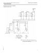
Wiring, Vitotronic 300-K Vitotronic 300, GW5B & MW1B Installation and Service Connection and Wiring Diagram Overview 106 A8 A10 A11 A12 X PCB LON communication module (accessory) Power supply unit PCB ON/OFF switch Electrical interfaces 5693 973 - 05 Legend A1 PCB, extension for heating circuits 2 and 3 with mixing valve A2 PCB low voltage A3 PCB 120V~ A6 Programming unit A7 Optolink PCB/emissions test switch
Wiring, Vitotronic 300-K Vitotronic 300, GW5B & MW1B Installation and Service Connection and Wiring Diagram (continued) PCB 120V~ 5693 973 - 05 Legend sÖ Heating circuit pump sA Circulation pump for DHW tank heating (accessory) sK DHW recirculation pump (on site) sL Shunt pump or distribution pump (on site) Power supply, 120V/60 Hz Central fault message Motor for 3-way mixing valve, primary store system abH Power supply connection for accessories F Fuse K1-K10 Relay S1 ON/OFF switch X Electrical inte
Wiring, Vitotronic 300-K Connection and Wiring Diagram Vitotronic 300, GW5B & MW1B Installation and Service (continued) PCB low voltage ) aG aJA aJB 108 No function No function No function Return temperature sensor T2 or Temperature sensor primary store system aVD aVG aVH LON S3 V1 V2 X External hook-up KM BUS participant External hook-up Connecting cable for data exchange (accessory) Emissions test switch “S” Fault indicator (red) ON indicator (green) Electrical interfaces 5693 973 - 05 Legend !
Wiring, Vitotronic 300-K Vitotronic 300, GW5B & MW1B Installation and Service Connection and Wiring Diagram (continued) PCB, extension for heating circuits 2 and 3 with mixing valve 5693 973 - 05 Legend ? Supply temperature sensors sÖ Heating circuit pumps fÖ Power supply gS Mixing valve motors K1-K6 Relay X Electrical interfaces 109
Components Vitotronic 300, GW5B & MW1B Installation and Service Sensors Boiler water, DHW tank, supply, return and room temperature sensors Note: H The supply temperature sensor can be used as a contact or immersion temperature sensor. Note: The supply temperature sensor in the mixing valve extension kit is a contact temperature sensor. H The room temperature sensor is connected at terminals 3 and 4 in the Vitotrol 300A.
Components Vitotronic 300, GW5B & MW1B Installation and Service Boiler Coding Card Boiler Boiler coding card Display in brief scan Part no. Vitocrossal 200, type CM2 1042 7841113 Mixing Valve Motor Kit Components: H Mixing valve motor (not for flanged mixing valve) H Connecting plug for the heating circuit pump H Supply temperature sensor as contact temperature sensor for measuring the supply temperature, with connecting cable 19 ft. (5.8 m) long. Changing the rotational direction (if required) 1.
Components Vitotronic 300, GW5B & MW1B Installation and Service Extension EA1 Accessory (optional) Duration of the heating program changeover Contact constantly closed: The changeover is active as long as the contact is closed. Contact only closed briefly via pushbutton: The changeover is enabled for the time selected in coding address “F2” in the “Heating circuit...” group.
Vitotronic 300, GW5B & MW1B Installation and Service Parts Lists Parts List Vitotronic 300, GW5B Ordering Replacement Parts: Please provide model no. from rating plate and serial no. when ordering replacement parts. Order replacement components from your Viessmann distributor.
Parts Lists Vitotronic 300, GW5B & MW1B Installation and Service Parts List Vitotronic 300-K Ordering parts The following information is required: H Serial no. (see type plate A) H Position number of the part (from this parts list) Obtain standard parts from your local supplier.
Specification Vitotronic 300, GW5B & MW1B Installation and Service Specification Vitotronic 300, GW5B Rated voltage 120V~ Rated frequency 60 Hz Rated current 2 x 6A~ Power consumption 10 W Permissible ambient temperature: During operation 32 to 104° F (0 to +40° C) Installation in living spaces or boiler rooms (standard ambient conditions) During storage and transport -4 to 149° F (−20 to +65° C) Rated relay output breaking capacity at 120V~ sÖ Primary pump, primary store system or Circulation pump – flue
5693 973 - 05 Technical information subject to change without notice. Printed on environmentally friendly (recycled and recyclable) paper.