Installation and service instructions for heating engineers VitotronicĂ300 typeĂKW3 Weather-compensated digital boiler and heating circuit control See applicability, pageĂ3.
General information Safety instructions Please follow these safety instructions closely to prevent accidents and material losses. Safety regulations Installation, initial start-up, inspection, maintenance and repairs must be carried out by a competent person (heating engineer/installation contractor). Observe all current safety regulations as defined by DIN, EN, DVGW, TRGI, TRF and VDE or locally applicable standards. See also the safety instructions sheet in the Vitotec Technical Guide.
General information/index Product information/applicability Vitotronic 300, type KW3 Only for integration/installation on/in Viessmann boilers. Valid for control units Part no. 7450 760 to part no. 7450 763 Index General information Safety instructionsĂ . . . . . . . . . . . . . . . . . . . . . . . . . . . . . . . . . . . . . . . . . . . . . . . . . . . . . . . . . . . . . . . . . . . . . . . . . . . . . . . . . . . . . . . . . . . . . . . . . . . . . . . . . . . . . . . . . .
Contents Index (cont.) Troubleshooting Faults with fault display at the programming unitĂ . . . . . . . . . . . . . . . . . . . . . . . . . . . . . . . . . . . . . . . . . . . . . . . . . . . 42 Downloading fault codes from the fault memory (error history)Ă . . . . . . . . . . . . . . . . . . . . . . 50 Faults without fault display at the programming unitĂ . . . . . . . . . . . . . . . . . . . . . . . . . . . . . . . . . . . . . . . . . . . . 51 Function description Boiler temperature controlĂ . . . . . .
Heating system designs System version 1 One direct connected heating circuit without mixer C D A1 A B A Boiler with control unit B Domestic hot water cylinder C Vitotrol remote control, Control module V or Vitocom 100; KM BUS distributor, only with several KM BUS users D Heating circuit without mixer A1 Required coding 5862Ă297ĂGB ĈĈĈĈĈ *1Standard Plug ! § % Outside temperature sensor Boiler temperature sensor DHW cylinder temperature sensor sÖĂA1 Heating circuit pump sA Circulation pump for DHW cy
Heating system designs System version 2 One mixer circuit D C M2 E B A Boiler with control unit B Domestic hot water cylinder C KM BUS distributor, only for several KM BUS users, e.g. Vitotrol remote control, extension kit or Vitocom 100 D Mixer circuit M2 E Mixer circuit extension kit Plug ! ? § % Outside temperature sensor Flow temperature sensor (standard delivery extension kit) Boiler temperature sensor DHW cylinder temp.
Heating system designs System version 3 One direct connected heating circuit without mixer and one mixer circuit E D C A1 M2 F A B A Boiler with control unit B Domestic hot water cylinder C KM BUS distributor, only for several KM BUS users, e.g.
Heating system designs System version 4 Two mixer circuits C E H G M2 M3 F D A 5862Ă297ĂGB B 8
Heating system designs System version 4 (cont.
Heating system designs System version 5 One direct connected heating circuit without mixer and two mixer circuits C K E H G A1 M2 M3 F D A 5862Ă297ĂGB B 10
Heating system designs System version 5 (cont.) A Boiler with control unit B Domestic hot water cylinder C Mixer circuit M2 D Extension kit for mixer circuit M2 E Mixer circuit M3 F Extension kit for mixer circuit M3 G KM BUS distributor H Mains power distributor K Heating circuit without mixer A1 Required coding 5862Ă297ĂGB ĈĈĈĈĈ Plug ! Outside temperature sensor ? Flow temperature sensor § Boiler temperature sensor % DHW cylinder temperature sensor aJ Return temp.
Installation Summary of electrical connections 5862Ă297ĂGB Illustration shows the bottom part of the control unit as viewed from the rear.
Installation Summary of electrical connections (cont.) Plug 230 V~ sÖ Heating circuit pump A1 sA Circulation pump for DHW cylinder loading (accessory) sK DHW circulation pump (on site) fÖ Mains power connection fA Burner gÖ Central fault message aBÖ External connections, e.āg.
Installation Inserting cables and applying strain relief 5. 3. 4. 2. 6. 1. 1. Remove knock-out tab from the control unit. 5. Secure the top part of the cable clamp. 2. Click the bottom part of the fixing clamp into place. 6. Blank off unnecessary knockouts in the part of the control unit with cable grommets (not cut out). 3. Cut out cable grommet. 5862Ă297ĂGB 4. Insert the cable through the grommet and insert cable grommet into the casing.
Installation Changing the high limit safety cut-out (if required) The high limit safety cut-out is supplied with a factory setting of 110 ºC. ¨ If adjusted to 100 ºC, do not set the control thermostat above 75 ºC. Adjustment to 100 ºC at EGO 2. A 1. 4. 3. A Slotted screw 1. Pull the fuse from its holder. 4. Turn the slotted screw until the slot points to 100 ºC (once adjusted, the high limit safety cut-out cannot be reset). 5862Ă297ĂGB 2. Unhook and remove the cover from its four locking tabs. 3.
Installation Changing the high limit safety cut-out setting (cont.) Adjustment to 100 ºC at Juchheim 2. 1. 5. 6. 4. 3. 4. Remove the nut. 2. Unhook and remove the cover from its four locking tabs. 5. Remove the high limit safety cut-out. 3. Remove reset button cover "E". 6. Turn the screw until the indicator points to 100 ºC. 5862Ă297ĂGB 1. Pull the fuse from its holder.
Installation Changing the control thermostat (if required) The control thermostat is supplied with a factory setting of 75 ºC. Do not set the control thermostat above 75 ºC if the high limit safety cut-out has been adjusted to 100 ºC. Change to 87 ºC/95 ºC 2. 3. 1. 1. Lever out and remove rotary selector "R". 5862Ă297ĂGB 2. Using a pair of pointed pliers, break off the cams between "75" and "90" or "95" from the stop dial, which are identified in the drawing. 3.
Installation Inserting the boiler coding card Only use the boiler coding card included with the boiler product documentation. Boiler Coding Part no. card Vitola 111 F1 7818 916 Vitola 200 Vitola 222 Vitorond 200, type VR2 Vitorond 222 E1 7818 915 Vitogas 300, type GS3 Vitocrossal 300 Cb 7818 913 5862Ă297ĂGB Insert the boiler coding card through the cut-out in the cover into slot "X7".
Installation Sensor connection 145 15 3 5 191 1 143 5B 1 2 3 1 2 3 1 2 3 1 2 3 1 2 3 1 2 3 1 2 3 1 2 3 A B C D E A Flue gas temperature sensor B Boiler temperature sensor C DHW cylinder temperature sensor D Outside temperature sensor (interchange the cores) Installation location: H North or north-western wall, 2 to 2.
Installation Pump connection Available pump connections sÖ Heating circuit pump A1 sA Circulation pump for DHW cylinder loading sK DHW circulation pump Please note: Heating circuit pumps for mixer circuits are connected to the mixer circuit extension kit (see page 73). Pumps 230 V~ Pumps 400 V~ M 1~ N L L1 L2 L3 N PE M 3~ A B Rated current: 4 (2) A~ Recommended connection cable: H05VVĆF3G 0.75 mm2 or H05RNĆF3G 0.
Installation External connections on plug aBÖ ¨ The external connections must be volt-free. Plug aBÖ must remain plugged in, even if no connection is made. C D E ON ON A B A Jumper "STB" ć "STB" B Jumper "TR" ć "ON/TR" C External blocking (volt-free contact) D External start (volt-free contact) E Minimum pressure switch F Supplementary external safety equipment External burner blocking H Remove jumper "TR" Ĉ "TR". H Connect the volt-free contact. Opening this contact leads to a controlled shutdown.
Installation Connecting central fault messages Rated voltage: 230 V~ 50 Hz Rated current: 4 (2) A~ Recommended connection cable: H05VVĆF3G 0.75 mm2 or H05RNĆF 3G 0.
Installation External heating program changeover The manually pre-selected heating program can be modified via the volt-free contact. A Code "91" enables the external heating program changeover to be allocated to the individual heating circuits. Use control module V for the separate heating program changeover for 3 heating circuits (see page 91).
Installation Burner connection Modulating oil- and gas-fired boilers Connect the burner in accordance with DIN 4791. The burner cables are included in the standard boiler delivery. Max. current 4 (2) A.
Installation Burner connection (cont.) Burner without fan The burner cables are included in the standard boiler delivery. Max. current 4 (2) A.
Installation Burner connection (cont.) Two-stage/modulating burner extension The function extension is supplied with the boiler. Max. power consumption H two stage: 1 (0.5) A H modulating: 0.1 (0.05) A Observe coding addresses "02", "10" to "12", "15" to "18", "1A", "26" and "29" (see overview).
Installation Mains electrical connection Requirements Carry out the mains connection and all earthing measures (e.g. fault current circuit) in accordance with IEC 364, the requirements of your local electricity supplier, VDE regulations or all local and national regulations. The power supply to the control unit should be protected by a fuse with a max. rating of 16 A. Mains electrical isolator requirements (if necessary) For combustion equipment acc.
Installation Installing the top of the control unit 2. 7. 3. 6. 5. 1. 5862Ă297ĂGB 4.
Installation Opening the control unit 2. 5862Ă297ĂGB 1.
Initial start-up Steps Page 1. Checking the heating circuit allocationĂ . . . . . . . . . . . . . . . . . . . . . . . . . . . . . . . . . . . . . . . . . . . . . . . . . . . . . . . . . . . . . . . . . . . . . . . . . Ă30 2. Checking the high limit safety cut-outĂ . . . . . . . . . . . . . . . . . . . . . . . . . . . . . . . . . . . . . . . . . . . . . . . . . . . . . . . . . . . . . . . . . . . . . . . . 31 3. Changing the language (if necessary)Ă . . . . . . . . . . . . . . . . . . . . . . . . . . . . .
Initial start-up Further details regarding the individual steps (cont.) Checking the high limit safety cut-out The "TÜV" key must be held down during this test (position "h"). The control thermostatĂ"R" is now bypassed. The burner remains switched on until the boiler water temperature has reached the safety temperature and the high limit safety cut-out has switched off.
Initial start-up Further details regarding the individual steps (cont.) Checking outputs (actuators) and sensors Relay test 1 2 Relay test 3 1. Press K and d simultaneously for approx. two seconds. Relay test is activated. 2. Select the relay outputs with a or b. 3. Press d. Relay test is completed.
Initial start-up Further details regarding the individual steps (cont.) Adjusting heating curves The heating curves illustrate the relationship between the outside temperature and the boiler water or the flow temperature. To put it simply, the lower the outside temperature, the higher the boiler water or flow temperature. The room temperature again depends on the boiler water or the flow temperature. Settings in the as delivered condition: H Slope "n" = 1.
Initial start-up Further details regarding the individual steps (cont.) Changing slope and level (for each heating circuit separately) 1 2 1. Call up slope with I, value adjustable from 0.2 to 3.5 K; call up level with J; value adjustable from ć13 to +40 K. Slope 3 2. Change the value with a or b. 3. Confirm the set value with d. Boiler water temperature or flow temperature in °C A Changing the slope B Changing the level 3.5 110 B 1.4 A 0.
Initial start-up Further details regarding the individual steps (cont.) Adjusting the set room temperature (for each heating circuit separately) 1 2 3 1 2 3 Standard room temperature: Select the set day temperature with the set value adjuster. The value will be automatically adopted after approx. 2Ăseconds. Standard room temp. 20 Reduced room temperature: 1. Call up the night temperature with E. Reduced room temp. 14 2. Change the value with a or b. 3. Confirm the set value with d.
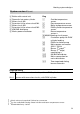
Service scans Service level summary Function Key combination Exit Page Adjusting the display contrast Press d and a simultaneously; the display will darken ćć ćć Press d and b simultaneously; the display will get lighter ćć ćć Temperatures, boiler coding card and short scanning Press K and G simultaneously for approx. two seconds Press d 37 Relay test Press K and d simultaneously for approx.
Service scans Temperatures, boiler coding card and brief scans 1 2 3 Outside temp. adj. -5 1. Press K and G simultaneously for approx. two seconds. 2. Select the required scan with a or b. 3. Press d. The following values can be scanned subject to the actual equipment level: H Outside temp. adj. H Outside temp. actual H Boiler temp. set H Boiler temp. actual H Flue gas temp. max. H Flue gas temp. actual H DHW temp. set H DHW temp. actual H Flow temp. set H Flow temp. actual H Return temp.
Operating mode boiler circuit 0 w/o remote control 1 with VitotrolĂ200 2 with VitotrolĂ300 3 5862Ă297ĂGB 4 Software version ć control unit 2 Software version ć remote control boiler circuit Software version ć programming unit Display acc.
Service scans Scanning operating conditions 1 2 Outside temperature 3 12 1. Press c. 2. Select the required operating condition scan with a orĂb. 3. Press c.
Service scans Scanning and resetting "Maintenance" display After limits have been reached, which were set up via coding addresses "1F", "21" and "23" (see page 105), the display indicates the flashing message "Maintenance", and the red fault lamp flashes. Please note: Set code "24:1" and then code "24:0", if maintenance is implemented before "Maintenance" is displayed; the set maintenance parameters for hours run and periods are reset to 0. 1 2 1. Press c. Maintenance scan is activated.
Service scans Scanning and resetting "Maintenance" display (cont.) After maintenance has been carried out 1. Reset code "24:1" (see page 105) to "24:0". The red fault lamp extinguishes. Please note: If the coding address "24" is not reset, a new "Maintenance" display will be shown on Monday at 07:00 hrs. 1 2 3 1 2 3. If required: H Press K and G simultaneously for approx. four seconds. H Reset "Flue gas temp. max." with e to the actual value (see pageĂ37). H Press d. 5862Ă297ĂGB 3 2.
Troubleshooting Faults with fault display at the programming unit 1 2 3 Fault Fr 57 The red fault lamp AĂflashes for all faults. A Fault Mo 1 w A 57 ºC Outside sensor DBG- 1 1 10 2 b7 Fault 1 Find the fault 1. Press c. 2. Call up further fault codes with a or b. The fault can be acknowledged with d. The fault message in the display will be hidden, but the red fault lamp A continues to flash.
Troubleshooting Faults with fault display at the programming unit (cont.) Outside sensor Fault display design Fault display DBG- 1 Fault code (for explanations see page 44) 1 10 Fault number (1 to 10) Fault symbol Fault display in plain text H Burner H Outside temperature sensor H Flow sensor H DHW cylinder sensor H Return sensor H Room temperature sensor H Flue gas sensor 5862Ă297ĂGB Calling up acknowledged fault messages Press d for approx. three seconds. The fault will then be displayed.
Troubleshooting Faults with fault display at the programming unit (cont.
Troubleshooting Faults with fault display at the programming unit (cont.
Troubleshooting Faults with fault display at the programming unit (cont.) Fault code System characteristics Cause Check 51 Control acc. to DHW cylinder temp. sensor 1 Short circuit DHW cylinder temp. sensor 2 Check DHW cylinder temperature sensor 2 (see page 68) 58 Cylinder loading Cable break pump ON: DHW cylinder temp. Set boiler temp. = set sensor 1 DHW cylinder temp., priority is cancelled Check DHW cylinder temperature sensor (see page 68) 59 Control acc. to DHW cylinder temp.
Troubleshooting Faults with fault display at the programming unit (cont.) Fault code System characteristics Cause Check ba Mixer (M2) continues to control bb Mixer (M3) continues to control Check the extension kit connections and coding.
Troubleshooting Faults with fault display at the programming unit (cont.) Fault code System characteristics c5 Control mode, Communication fault max.
Troubleshooting Faults with fault display at the programming unit (cont.
Troubleshooting Downloading fault codes from the fault memory (fault history) All faults are saved and may be scanned. 1 2 3 Fault history 1 18 1. Press G and d simultaneously for approx. two seconds. 2. Call up the individual fault codes with a or b. Fault history F11 18 Order of fault codes occurred 1 .. . . . . 10 Fault history d4 Last fault code .. . 10th last fault code All saved fault codes can be deleted with e. 3. Press d.
Troubleshooting Faults without fault display at the programming unit Boiler cold, burner does not start Set the emissions test switch to "h" H Pumps are not running → Check the supply voltage (mains isolator, mains supply cable, plug fÖ, ON switch, fuse F1, 6.3ĂA (slow). If the F1, 6.3ĂA (slow) fuse has blown: 1. Disconnect all 230 V plugs (pumps, burner, mixer motors etc.). 2. Replace the F1 fuse. 3. To determine the faulty device, reconnect all 230 V in sequence, until the faulty device is located.
Troubleshooting Faults without fault display at the programming unit (cont.) Boiler water temperature too high or too low Compare the actual and the set boiler water temperature H Set value too high or too low → Check the settings of the time switch, the heating curves and the coding addresses. Check the set value adjuster and the remote control (if installed): 1. Preselect a high day temperature and a low night temperature. 2.
Troubleshooting Faults without fault display at the programming unit (cont.) Boiler hot enough, but the heating circuit pumps will not run Set the emissions test switch to "h" H Pumps are running → No pump control: Check heating curves, set values and heating circuit pump logic, possibly also external hook-up (control module V, solid fuel boiler, etc.) or high DHW demand. H Pumps are not running → Is plug sÖ live between Lā and N? No Yes Check fuse F2, 4ĂA (slow). If the fuse has blown: 1.
Function description Boiler temperature control Brief description The boiler water temperature is regulated by starting and shutting down the burner. In the "as delivered condition", the switching differential is ±2 K, relative to the current set value. The set boiler water temperature is determined from the set flow temperature of the heating circuit with and without mixer and the set DHW temperature, and is subject to the installed boiler and the heating and control equipment.
Function description Boiler temperature control (cont.) Auxiliary circuits H Two-stage/modulating burner: An extension can be connected for controlling a two-stage/modulating burner. H External hooking up: The following external hook-ups can be implemented with the control module V: Ĉ Separate heating program changes for heating circuits Please note: The heating program changeover can be effected for one heating circuit or several heating circuits simultaneously via plug aVD, see coding address "91".
Function description Heating circuit control Brief description The control unit provides control circuits for one heating circuit without mixer and two mixer circuits. The set flow temperature of every heating circuit results from the outside temperature, the set room temperature, the operating mode and the heating curve. The flow temperature of heating circuits without mixer is equal to the boiler water temperature.
Function description Heating circuit control (cont.) Domestic hot water temperature H With DHW priority: The set flow temperature will be set to 0 ºC whilst the cylinder is being loaded. The mixer closes, and the heating circuit pumps are switched OFF. H Without DHW priority: The heating circuit control unit continues to operate with the same set value. H With modulating priority (only in conjunction with a mixer circuit): The heating circuit pump remains switched ON.
Function description Heating circuit control (cont.) Extended economy circuit The heating circuit pump is switched OFF, and the set flow temperature is set to 0 ºC, if H the outside temperature exceeds the value selected via coding address "A6" H the set room temperature is reduced via coding address "A9".
Function description Flow temperature control Differential temperature: The differential temperature may be adjusted via coding address "05"; as delivered condition: 8 K. The differential temperature is that value by which the boiler water temperature should at least be higher than the currently required flow temperature of the mixer circuit. H System with only one mixer circuit: The set boiler water temperature will be automatically controlled to 8 K above the set flow temperature.
Function description Heating circuit control (cont.) Upper control limit Electronic maximum limit Setting range: 1 to 127 ºC Changes via coding address "C6". Please note: The maximum limit is no replacement for the underfloor heating system high limit thermostat. High limit thermostat for underfloor heating systems: The high limit thermostat switches the heating circuit pump OFF, if the set value has been exceeded. In such cases, the flow temperature reduces only slowly, e.g.
Function description DHW cylinder temperature control Brief description The DHW cylinder temperature control operates at a constant temperature. It is the result of starting and stopping the circulation pump for DHW cylinder loading. The switching differential is ±2.5 K. Coding addresses that influence the boiler water temperature control are 55, 56, 58 to 62, 64, 66, 70 to 75, 7F, A2. For a description, see the coding overview.
Function description DHW cylinder temperature control (cont.) In conjunction with coding address "7F" "7F:1" Detached house: H Automatic operation For systems with two or three heating circuits, the heating times for heating circuit 1 are applied. H Individual time program The switching times for DHW loading and the DHW circulation pump have the same effect on all heating circuits.
Function description DHW cylinder temperature control (cont.) Control sequence DHW cylinder goes cold (set value ć2.5 K, adjustable via coding address "59") DHW priority H With DHW priority: (coding "A2:2"): The set flow temperature will be set to 0 ºC whilst the cylinder is being loaded. The mixer closes, and the heating circuit pumps are switched OFF. H Without DHW priority: The heating circuit control unit continues to operate with the same set value.
Function description DHW cylinder temperature control (cont.) The DHW cylinder is hot (set value +2.5 K) The set boiler water temperature is returned to the weather-compensated value. Pump run-on H The circulation pump for DHW cylinder loading runs on after cylinder loading, until Ĉ the difference between the boiler water and the DHW temperature is less than 7 K or Ĉ the weather-compensated set boiler water temperature is achieved or Ĉ the set DHW temperature has been exceeded by 5 K.
Components Components from the parts list For parts list see page 124. Main PCB The main PCB comprises: H Relay for selecting pumps and burner H Connections for sensors, actuators, burner and mains connection for accessories H Fuse F2, 4A (slow) Printed circuit board All data is processed and outputs (relay) are selected. Power supply unit PCB The power supply unit PCB comprises the low voltage supply for all electronic equipment.
Components Components from the parts list (cont.) TÜV key High limit safety cut-out For testing the high limit safety cut-out. For a description see page 31. H Type STB 56.10525.570, Messrs. EGO, DINĂSTBĂ10602000 or EMĆ80ĆV/b7Ć1 60002843, Messrs.
Components Components from the parts list (cont.) Control thermostat H Type TR 55.18015.050, Messrs. EGO, DINĂTR11032002 or EMĆ1/b1; 60002847, Messrs. Juchheim, DIN TR 77798 H Set to 75 ºC in the "as delivered condition", adjustable to 87 and 95ĂĂºC (see page 17) Expansion module Viessmann 2-wire BUS PCB for data exchange with additional heating circuit control units Vitotronic 050 or solar heating controllers, as well as for connecting to overriding management systems via Vitocom 200 or 300.
Components Components from the parts list (cont.) Boiler temperature sensor and cylinder temperature sensor Connection See page 19. Checking the sensor 1. Pull plug §, % or %B off. 760 740 720 700 680 660 640 Resistance in 620 600 580 560 540 Boiler water or DHW cylinder temperature in °C Resistance in W 40 50 60 578 597 616 3. Compare measurement with the actual temperature displayed (for scanning, see pageĂ37). Check the installation and replace sensor, if necessary, in case of severe deviation.
Components Components from the parts list (cont.) Outside temperature sensor Connection See page 19. Checking the outside temperature sensor 1. Pull plug ! off. 2. Check the sensor resistance at terminals "1" and "2" of the plug. 600 580 560 Outside Resistance temperature in °C in W 540 ć10 ć10 ć20 520 500 Resistance in 480 3. Disconnect wires from the sensor, if actual values deviate severely from the curve.
Components Radio clock receiver, part no. 7450 563 The radio clock receiver provides fully automatic time setting for the control unit and remote control (if connected). E A B C D 1 A Outside temperature sensor B Radio clock receiver C Green LED D Red LED E Aerial Connection 2-core cable with a maximum length of 35 m and a cross-section of 1.5Ămm2 (copper).
Components Flue gas temperature sensor, part no. 7450 630 Connection The sensor is plugged into socket "15" at the control unit. Checking the flue gas temperature sensor 1. Pull plug aG off. 1020 980 940 900 860 820 780 700 660 Resistance in Flue gas temperature in ºC Resistance in W 180 160 200 650 800 880 3. Compare measurement with the actual temperature displayed (for scanning, see pageĂ37). In case of severe deviation, check the installation and replace sensor, if necessary.
Components Mixer circuit extension kit (cont.) Mixer extension Electrical connections summary A B CD EF G 141 17 2 A Mixer extension B H Mixer motor for part no. 7450 069 H Wall mounting base for part no.
Components Mixer circuit extension kit (cont.) Pump connection 230 V~ Pump connection 400 V~ M 1~ N L L1 L2 L3 N PE 20 20 A A A To the extension kit B C A To the extension kit B Contactor C Three-phase pump 5862Ă297ĂGB Specification see page 20.
Components Mixer circuit extension kit (cont.) Control unit connection Mains electrical connection A A 40 C C B B A To the extension kit B To the control unit or the mains distributor C Mains cable Please note: Use KM BUS distributor (see page 93) when connecting several BUS users. Please note: Use the mains distributor when using two extension kits (see page 94).
Components Mixer circuit extension kit (cont.) Mixer motor, part no. 7450 657 (only when using the extension kit, part no. 7450 059) The mixer motor is a synchronous single phase motor with reversible rotation, together with gearbox and two limit switches.
Components Mixer circuit extension kit (cont.) Mixer motor, part no. 9522 487 (only when using the extension kit, part no. 7450 059) The mixer motor is a synchronous single phase motor with reversible rotation, together with gearbox and two limit switches.
Components Mixer circuit extension kit (cont.) Mixer motor, part no. 9522 488 (only when using the extension kit, part no. 7450 059) The mixer motor is a synchronous single phase motor with reversible rotation, together with gearbox and two limit switches.
Components Mixer circuit extension kit (cont.) Changing the rotational direction H For the installation examples on page 79 and H for systems with Modular Divicon the rotational direction must be changed. ¨ĂSafety instruction Switch OFF the mains power supply before opening the device. Switching the mains switch on the mixer extension OFF is not safe enough. B I II A 1. Open mixer extension. Rotational direction switch: Position I: As delivered condition Position II: Change the rotational direction 2.
Components Mixer circuit extension kit (cont.) Change the rotational direction for these installation examples (see page 78).
Components Mixer circuit extension kit (cont.) Coding (DIP switches on the main PCB of the mixer extension) S1.4 must always be set to "OFF". Affects mixer circuit M2 S1 As delivered condition When connecting a return temperature sensor S1.3 to "ON" S1 Affects mixer circuit M3 S1.1 to "ON" S1 Specification 80 H in storage and transport: Rated capacity of relay outputs at 230 V~ for H Heating circuit pump sÖ: H Mixer motor: H Total : ć20 to +65ĂºC 4āā(2)ĂA~ 0.2āā(0.1)ĂA~ max.
Components Contact temperature sensor, part no. 7450 642 For recording the flow and return temperature. Connection The sensor is plugged into socket "2" or "17" of the mixer extension. Check sensor 1. Pull plug ? or aJ off. 740 720 700 680 660 640 600 580 560 540 20 30 40 50 60 70 80 90 100 Flow or return temperature in ºC Flow or return temperature in °C Resistance in W 30 40 60 569 592 643 3. Compare measurement with the actual temperature displayed (for scanning, see page 37).
Components High limit thermostat for limiting the maximum temperature Immersion thermostat, part no. 7151 728 Contact thermostat, part no. 7151 729 20 C Electromechanical high limit thermostat according to the liquid expansion principle. Switches OFF when the set heating circuit pump value is exceeded. Specification Setting range: Connection terminals: Screw terminals for 1.5 mm2 Switching differential H Immersion thermostat: max. 11 K H Immersion thermostat: max. 14 K DIN reg. no.
Components Remote control Vitotrol 200, part no. 7450 017 (with integral room temperature sensor for hooking up room temperature in conjunction with a mixer circuit) Setting the: H Day temperature, H Heating program, H Economy and party mode. Function changes can be effected via coding addresses "A0", "b0" to "b10", "C0" to "C2", "E1" and "E2" (see overview). Connection 2-core cable (total cable length max.
Components Remote control (cont.) When connecting a separate room temperature sensor, set DIP switch "S6.3" to "ON". S6 S6 ON A 1234 A PCB DIP switches (rear of the top of the case) Remote control affects Coding switch setting System circuit A1 As delivered (Heating circuit condition selection key !) Mixer circuit M2 (Heating circuit selection key ?) Specification Power supply via KM BUS.
Components Remote control (cont.) Vitotrol 300, part no. 7450 790 (with integral room temperature sensor for hooking up room temperature in conjunction with a mixer circuit) Setting the: H Day and night temperature, H Holiday program, H DHW temperature, H Switching times, H Heating program, H Economy and party mode. Function changes can be effected via coding addresses "A0", "b0" to "b10", "C0" to "C2", "E1" and "E2" (see overview) . Connection 2-core cable (total cable length max.
Components Remote control (cont.) When connecting a separate room temperature sensor, set DIP switch "S30.3" to "ON". A S30 A PCB DIP switches (rear of the top casing) Remote control affects Coding switch setting System circuit A1 (Heating circuit selection key !) As delivered condition Mixer circuit M2 (Heating circuit selection key ?) 5862Ă297ĂGB Mixer circuit M3 (Heating circuit selection key §) Specification Power supply via KM BUS.
Components Remote control (cont.) Connecting several remote control units When you connect several remote control units to the control unit, use the KM BUS distributor, part no. 7415 028, which is available as accessory, or use a socket (on-site provision). Version 1 C D max. 15 m E max. 15 m max.
Components Remote control (cont.) Version 2 max. 15 m C max. 15 m max. 15 m E D F B 145 A D Vitotrol 2 E Vitotrol 3 F Further KM BUS users H If several remote control units and additional KM BUS users are connected, make the connections via a socket (on-site) as shown in the diagram. H The total length of all KM BUS cables should be limited to 50 m.
Components Room temperature sensor, part no. 7408 012 The room temperature sensor measures the actual room temperature, if the remote control unit cannot be installed in a suitable location. 1 2 3 4 Connection 2-core cable with a maximum length of 35 m and a cross-section of 1.5Ămm2 (copper). Set DIP switchĂ3 on the remote control unit to "ON" (see pages 84 and 86).
Components Room temperature sensor, Part no. 7408 012 (cont.) Check the room temperature sensor 1. Disconnect the wires from the sensor. 600 590 580 570 560 550 Resistance in 540 530 520 510 500 0 5 10 15 20 25 30 35 40 Room temperature in ºC 2. Check the sensor resistance at terminals "9" and "13b". Room temperature in ºC Resistance in W 10 15 25 522 534 557 3. Compare measurement with the actual temperature displayed (for scanning, see pageĂ37).
Components Control module V, part no. 7143 513 Control module V for functional expansion of the control unit. Observe the coding addresses "32", "33" and "74" (see overview). Control module V is recognised automatically by the control unit (coding "94:2"). A X3 X4 X5 X6 X7 X8 X9 X1 X2 B A Control module V terminal arrangement box B To the control unit 5862Ă297ĂGB ¨ Do not alter the allocation of connections to sockets in control module V.
Components Control module V, Part no. 7143 513 (cont.) Plug a-D DE1 External heating program change for heating circuits without mixer Closing the contact changes the boiler circuit to constantly reduced mode. DE2 External heating program change for mixer circuit M2 Closing the contact changes mixer circuit M2 to constantly reduced mode. DE3 External burner blocking This function only affects the burner. Burner start is blocked, if the contact is closed.
Components KM BUS distributor, part no. 7415 028 The connection between the control unit and the remote control, the remote monitoring equipment and control module V is provided by the KM BUS distributor. X1 X2 X3 X4 X5 X6 X7 5862Ă297ĂGB 6 5 4 3 2 1 A KMĂBUSĂdistributorĂarrangementĂbox B Terminals for the connection of additional KM BUS users (connection at terminals "X8.1" and "X8.2", "X8.3" and "X8.4" or "X8.5" and "X8.
Components Mains power distributor, part no. 7415 030 Mains distributor to supply electrical accessories. The ON/OFF switch on the control unit isolates the equipment connected via the mains distributor. A K1 X2 NN L L 156 156 156 E D 40 8 7 6 5 4 3 2 1 X4 X1 C B *1Remove 94 D Accessory connections E Fuses the jumper, if a mains isolator is connected to these terminals.
Components Boiler coding card To match the control unit function to the boiler (see page 18). Burner connection cables For boilers with H oil- and gas-fired pressure jet burners, for connection, see page 24. H burner without fan, for connection, see page 25. Function extension for connection to a two-stage/modulating burner, part no. 7404Ă960; for connection, see page 26. 5862Ă297ĂGB For part no., see parts list.
Components Vitoair draught stabiliser, part no. 7338 725 and 7339 703 A B A To control unit B To burner Colour coding to DIN/IEC 757 BK black GN/YE green/yellow Function check Press rotary button C on the motor and turn to the central position. H Enable the burner from the control unit → The rotary button should move towardsĂ"3". The motor enables the control disc, and the flue pipe is open. H Burner OFF → The rotary button should move towardsĂ"5".
Components Motorised flue gas damper, part no. 7252 819 ON ON A To control unit B Flue gas damper motor Colour coding to DIN/IEC 757 BK black Function check Press rotary button C on the motor and turn to the central position. H Enable the burner from the control unit → The rotary button should move towardsĂ"3". The motor moves the flue gas damper into the "OPEN" position. H Burner OFF → The rotary button should move towardsĂ"5".
Coding Resetting codes into the "as delivered condition" 1 2 3 Code 2 Cod. 2 1. Press L and G simultaneously for approx. 2 seconds. 2. Press e. "Base setting? Yes", confirm with d. Select "Base setting? Yes" with a or "Base setting? No" with b. Code 1 Calling up code 1 1 2 3 1 2 3 Code 1 Cod. 1 System diagram Cod. 1 1. Press K and L simultaneously for approx. two seconds. 2. Select the required coding address with a or b; the address flashes; confirm with d; the value flashes. 3.
Coding Code 1 (cont.
Coding Code 1 (cont.) Coding in the delivered condition Possible change Max. boiler temp.
Coding Code 2 The summary from page 103 lists all possible coding addresses. The control unit display only shows those coding addresses, which may be adjusted in accordance with the relevant system version and equipment level. System diagram Cod. 00 The coding addresses are grouped in accordance with the adjacent sequence. Boiler/burner Cod. 02 to 33 Domestic hot water Cod. 55 to 75 General Cod. 7F to 98 Boiler circuit A1 Cod. A0 to FF Mixer circuit M2 Cod. A0 to FF 5862Ă297ĂGB Mixer circuit M3 Cod.
Coding Code 2 (cont.) Calling up code 2 1 2 3 1 2 3 Code 2 Cod. 2 System diagram Cod. 2 1. Press L and G simultaneously for approx. two seconds; confirm with d. 2. Select the required coding address with a or b; the address flashes; confirm with d; the value flashes. 3. Change the value with a or b; confirm with d. The display briefly indicates "Adopted", then the address flashes again. Call up further addresses with a or b. 5862Ă297ĂGB 4. Press L and G simultaneously for approx. one second.
Coding Code 2 (cont.) Summary Coding in the delivered condition Possible change System diagram (see page 99) Boiler/burner 02 : ăă0 Ă Ă Operation with a single g burner stage 02 : ăă1 Operation with a two-stage burner 02 : ăă2 Operation with a modulating burner Ă Ă Ă Ă 03 : ăă0 Do not adjust 04 : ăă0 Switching hysteresis 4ĂK (Kelvin) (see pageĂ123) Ă Ă Ă Ă 04 : ăă1 Ă Ă 04 : ăă2 Ă Ă Heat demand-dependent switching hysteresis (see pageĂ123).
Coding Code 2 (cont.) Coding in the delivered condition Possible change Boiler/burner (two-stage) (cont.
Coding Code 2 (cont.) Coding in the delivered condition Possible change Boiler/burner 1F : ăă0 Ă Ă With flue gas temp.
Coding Code 2 (cont.) Coding in the delivered condition Possible change Boiler/burner (cont.
Coding Code 2 (cont.) Coding in the delivered condition Possible change Domestic hot water (cont.) 61 : ăă0 The circulation pump will be started subject to the boiler temperature 61 : ăă1 Circulation pump starts immediately 62 : ă10 Circulation pump with a max. of 10 minutes run-on 62 : ăă0 Circulation pump without run-on 62: ăă1ă to 62 : ă15 Run-on time adjustable from 1 to 15 minutes 64 : ăă0 No DHW heating, DHW circulation pump OFF 64 : ăă1 DHW heating and DHW circulation pump acc.
Coding Code 2 (cont.) Coding in the delivered condition Possible change Domestic hot water (cont.) 70 : ăă0 DHW circulation pump ON 70 : ăă1 acc. to time program when DHW loading is enabled 71 : ăă0 DHW circulation pump: ON acc.
Coding Code 2 (cont.) Coding in the delivered condition Possible change General 7F : ăă1 Detached house 7F : ăă0 Multi-occupancy house. Separate settings for holiday and time programs are possible for DHW loading (see page 62) for every heating circuit. 80 : ăă1 A fault message g is displayed, provided a fault persists for at least 5 seconds 80 : ăă0 Immediate fault message 80 : ăă2 to 80 : 199 The minimum fault duration, until a message is displayed, is adjustable from 10 to 995 seconds.
Coding Code 2 (cont.) Coding in the delivered condition Possible change General (cont.
Coding Code 2 (cont.) Coding in the delivered condition Possible change General (cont.
Coding Code 2 (cont.
Coding Code 2 (cont.) Coding in the delivered condition Possible change Boiler circuit/mixer circuit (cont.) A4 : ăă0 With frost protection A4 : ăă1 No frost protection, Adjustment only possible if code "A3: Ĉ9" has been selected. ¨ĂObserve the note for coding address "A3".
Coding Code 2 (cont.) Coding in the delivered condition Possible change Mixer circuit A7 : ăă0 Ă Ă Without mixer economy function A7 : ăă1 With mixer economy function (extended heating circuit pump logic): Heating circuit pump also OFF, if the mixer was closed longer than 12 mins. Heating circuit pump ON, H if the mixer changes to control mode or H after DHW cylinder loading (for 20 minutes) or H if there is a risk of frost A9 : ăă1 to A9 : ă15 Incl.
Coding Code 2 (cont.) Coding in the delivered condition Possible change Boiler circuit/mixer circuit (cont.) b0 : ăă0*1 Incl.
Coding Code 2 (cont.) Coding in the delivered condition Possible change Boiler circuit/mixer circuit (cont.) b5 : ăă0*1 Incl. remote control: Without room temperature- b5 : ăă1 dependent heating circuit pump logic function Ă Ă Ă Ă b6 : ăă0*1 With remote control and for the heating circuit, heating with room temperature hook-up must be encoded: Without quick heat-up/ b6 : ăă1 quick setback H Heating circuit pump OFF, if the actual room temperature (RTactual) is 2.
Coding Code 2 (cont.) Coding in the delivered condition Possible change Boiler circuit/mixer circuit (cont.
Coding Code 2 (cont.) Coding in the delivered condition Possible change Mixer circuit C4 : ăă1 Ă Ă Mixer algorithm Standard C4 : ăă0 Ă Ă C4 : ăă2 and C4 : ăă3 Ă Ă Mixer algorithm faster Mixer algorithm slower Ă Ă Boiler circuit/mixer circuit C5 : ă20 Ă Ă Electronic minimum flow temperature limit 20 ºC C5 : ăă1 to C5 : 127 Minimum limit adjustable from 1 to 127 ºC C6 : ăă1 to C6 : 127 Max.
Coding Code 2 (cont.
Coding Code 2 (cont.) Coding in the delivered condition Possible change Boiler circuit/mixer circuit E9 : ă20 Ă Ă F0 : ăă0 Ă Ă Speed of the variable speed pump = 20 % of max. speed in reduced mode E9 : ăă0 to E9 : 100 Speed adjustable from 0 to 100 % of max. speed F1 : ăă1 to F1 : ăă4 Screed drying function adjustable in accordance with four temperature-time profiles (see page 122).
Coding Code 2 (cont.) Coding in the delivered condition Possible change Boiler circuit/mixer circuit F2 : ăă0 Ă Ă No time limit for party mode*1 F2 : ăă1 to F2 : ă12 Ă Ă Ă Ă Time limit for party mode adjustable between 1 and 12 hours*1 *1The 5862Ă297ĂGB party mode ends automatically in heating program "rw", when the system changes over to operation with standard room temperature.
Coding Screed drying function diagram Coding see page 120.
Coding Burner switching hysteresis Coding see page 103. Switching hysteresis 4 K (code "04 : 0") Burner Ă Ă On Time Off +2 Set -2 low heat demand average heat demand high heat demand Heat demand-dependent switching hysteresis ERB50 function (code "04 : 1") Subject to heat demand, values between 6 and 12 K result. Burner Ă Ă On Time Off +9 +3 Set -3 low heat demand average heat demand high heat demand ERB80 function (code "04 : 2") Subject to heat demand, values between 6 and 20 K result.
Parts list Parts list Parts 001 Cable clamp 004 Stop dial for control thermostatĂ"R" 005 Cover plug for high limit safety cut-outĂ"E" 010 Fascia cover 011 Control panel lower r.h. side 013 Upper casing body (drawer) 014 PCB cover, comp.
Parts list Parts list (cont.
Connection and wiring diagram Connection and wiring diagram This wiring diagram only applies in conjunction with Viessmann products. Subject to technical modifications. 127/128 5862Ă297ĂGB 6.
Connection and wiring diagram Connection and wiring diagram (cont.
Appendix Specification Rated voltage: Rated frequency: Rated current: Power consumption: Safety class: Protection: Function: 230 V~ 50 Hz 6 amp ~ 5W I IP 20 D acc. to ENĂ60529, safeguard through appropriate design and installation Type 1 B acc.
Appendix Settings and equipment Tick off the adjusted function. Function in as delivered condition Modified function HighĂlimitĂsafetyĂcut-outĂ"E"ĂsetĂtoĂ110ĂºC j Changed to .ā.ā.ā.ā.ā..ā.ā..ā.ā..ā.ā..ā.ā..ā.ā. ºC Control thermostatĂ"R" set to 75 ºC j Changed to .ā.ā.ā.ā.ā..ā.ā..ā.ā..ā.ā..ā.ā..ā.ā.
Appendix Settings and equipment (cont.) Function in as delivered condition Heating circuit pumps In heating programĂ"rw", the heating circuit pumps are switched OFF, when the outside temperature exceeds the set room temperature by more than 1ĂK. In heating programĂ"w" ć the heating circuit pumps are only started when there is a risk of frost, ć any connected mixer stays closed (when there is a risk of frost, it changes to control mode).
Appendix Settings and equipment (cont.) Function in as delivered condition Mixer circuit M2 Heating mode/reduced mode weather-compensated Mixer circuit M3 Heating mode/reduced mode weather-compensated Frost protection Frost protection active from 1 ºC j Heating mode: weather-compensated, Red. mode: with room temperature hook-up j Heating mode: with room temperature hook-up, Red. mode: weather-compensated j Heating mode/ Red. mode: with room temperature hook-up j Heating mode: weather-compensated, Red.
Appendix Settings and equipment (cont.) Function in as delivered condition Modified function Heating system with DHW heating: H DHW is loaded from the times when DHW heating is enabled H With DHW priority j Without DHW priority Heating system with DHW heating (cont.): H Setting range for DHW temperature 10 to 60 ºC j Setting range for DHW temperature 10 to 95 ºC j Circulation pump starts immediately H The circulation pump for DHW cylinder loading runs on for a max.
Appendix Settings and equipment (cont.
Appendix Keyword index B Boiler coding card, 18, 37, 95 Boiler temperature control, 54 Boiler temperature sensor, 12, 68 Brief scan, 37 Burner, H connecting, 24 H connection cables, 95 H external start-up/shutdown, 21 H switching hysteresis, 103, 123 C Calling up fault messages, 42 Central fault message, 22, 111 Coding, H code 1, calling up, 98 H code 2, calling up, 102 H overview, 103 H resetting codes to as delivered condition, 98 Coding summary, 103 Commissioning, implementation, 30 Components, 65 Co
Appendix Keyword index (cont.) H Heating circuit allocation, 30 Heating circuit control unit, 56 Heating circuit pump logic function, 57, 113 Heating circuit pump, var.
Appendix Keyword index (cont.) T Time, 39 Time program,Ă56 Temperature scanning, 37 TÜV key, 66 U Underfloor heating, 58, 119 W Weather-compensated mode, 115 Winter/summer, 109 Wiring diagram, 127 Work on the equipment, 2 Viessmann Werke GmbH & Co DĆ35107 Allendorf Tel: +49 6452 70Ć0 Fax: +49 6452 70Ć27 80 www.viessmann.de Ă Ă Ă Viessmann Limited Hortonwood 30, Telford Shropshire, TF1 7YP, GB Tel: +44 1952 675000 Fax: +44 1952 675040 email: info-uk@viessmann.