Installation and service instructions VIESMANN for contractors Vitotronic 100 Type HC1B Digital boiler control unit Vitotronic 300-K Type MW2B Weather-compensated, digital cascade control unit For applicability, see the last page VITOTRONIC 100 VITOTRONIC 300-K 5601 090 GB 7/2011 Please keep safe.
Safety instructions Safety instructions Please follow these safety instructions closely to prevent accidents and material losses. Safety instructions explained Danger This symbol warns against the risk of injury. ! Please note This symbol warns against the risk of material losses and environmental pollution. Note Details identified by the word "Note" contain additional information.
Safety instructions Safety instructions (cont.) If you smell flue gas Danger Flue gas can lead to life-threatening poisoning. ■ Shut down the heating system. ■ Ventilate the boiler room. ■ Close all doors leading to the living space. Working on the system ■ When using gas as fuel, also close the main gas shut-off valve and safeguard against unauthorised reopening. ■ Isolate the system from the power supply and check that it is no longer 'live', e.g.
Index Index Installation instructions Preparing for installation System version ID: 4605016................................................................................ 7 Installation, Vitotronic 100 Installation information for the Vitotronic 100....................................................... 10 Installing a cascade communication module........................................................ 10 Installation, Vitotronic 300-K Overview of electrical connections on the Vitotronic 300-K..........
Index Index Scanning operating data...................................................................................... 44 Brief scan............................................................................................................. 44 Service scans, Vitotronic 300-K Calling up the service menu................................................................................. Exiting the service menu......................................................................................
Index Index (cont.) Radio clock receiver, part no. 7450 563............................................................... 130 Extension kit, mixer, part no. 7441 998................................................................ 132 Mixer motor, part no. 9522 487............................................................................ 133 Mixer motor, part no. Z004 344............................................................................
Preparing for installation System version ID: 4605016 Multi boiler system with several heating circuits with mixer and low loss header (with/without DHW heating) Hydraulic installation scheme 43 --6/2-44 --6/20-45 --6/52-- 7 --6/28-- 3 11 --6/5-- 51 52 45 --6/52-- 53 50 --230V---20-- 2 4 4 --5---1---143---KM BUS---2-- --KM BUS-- 5 1 6 --230V---21---28---50---20---52-- --KM BUS-- 10 --5/20-- 44 --6/20-- 16 --230V---20-- KW --6/21-- --2/20-- 43 --6/2-- --6/2-- 12 --- 40 --6/1-
Preparing for installation System version ID: 4605016 (cont.) Equipment required Pos.
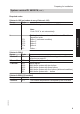
Preparing for installation System version ID: 4605016 (cont.) Required codes Vitotronic 100 (set codes at every Vitotronic 100) Group Code 2 01:2 Multi boiler system with Vitotronic 300-K Note Code "00:0" is set automatically. 07:1 07:2 07:3 07:4 07:... Vitotronic 300-K Group Code "General" 00:... "General" "Cascade" 7E:1 35:1 35:2 35:3 35:4 35:... Setting the boiler number at the Vitotronic 100 of the respective boiler Boiler 1 (delivered condition) Boiler 2 Boiler 3 Boiler 4 Boiler ...
Installation, Vitotronic 100 Installation information for the Vitotronic 100 For installation, commissioning, maintenance and service of Vitodens 200-W with Vitotronic 100: see separate installation instructions and service instructions. If a DHW cylinder is to be integrated into the system, make the connection at the Vitotronic 300-K (or, if installed, at the Vitotronic 200-H). Installing a cascade communication module 5601 090 GB The communication module is part of the standard delivery.
Installation, Vitotronic 100 Installing a cascade communication module (cont.) Opening the control unit casing 2. 2x Installation 3. 1. 5. 5601 090 GB 4.
Installation, Vitotronic 100 Installing a cascade communication module (cont.) Installation of the communication module 7. 5601 090 GB 6.
Installation, Vitotronic 300-K Overview of electrical connections on the Vitotronic 300-K 52 52 20 20 2 2 M3 M2 M3 M2 M3 M2 145 145 1 3/2 5 A 5 B 17 B 143 146 5601 090 GB Installation LON 28 21 52 A1 20 A1 29 50 40 156 PCB, extension for heating circuits 2 and 3 (accessory) ? M2/M3 Flow temperature sensor sÖ M2/M3 Heating circuit pump gS M2/M3 Mixer motor aJB Main circuit board, LV Outside temperature sensor ! §/? Flow temperature sensor, common heating flow/low loss header Cylinder temperature s
Installation, Vitotronic 300-K Overview of electrical connections on the… (cont.) ■ When connecting external switching contacts or components to the safety LV of the control unit (aVD and aVH), observe the requirements of safety category II, i.e. 8.0 mm air and creep path or 2.0 mm insulation thickness from 'live' components. ■ For all on-site components (incl. PC/ laptops), ensure safe electrical separation to EN 60 335 or IEC 65.
Installation, Vitotronic 300-K Installing the mounting bracket and control unit back Installation 3. 2. 5601 090 GB 1.
Installation, Vitotronic 300-K Installing a PCB, extension for heating circuits 2 and 3 Accessory, part no. 7164 403 Separate installation instructions Inserting cables/leads and applying strain relief A D C D B C Plug-in connection diagram D Fem. mouldings for plug-in connection diagram 5601 090 GB A Cables with moulded strain relief B On-site cables; strip up to 100 mm insulation.
Installation, Vitotronic 300-K Making the connections to the Vitotronic 100 The cascade communication module must be fitted into every Vitotronic 100 (see page 10). A 145 A B C C 1 2 3 4 1 2 3 4 KMK1 KMK2 D A Plug aVG for Vitotronic 300-K B 2-core cable (cross-section 2 x 0.5 mm2, total length 50 m) D Terminal strip on the cascade communication module in the Vitotronic 100 5601 090 GB A Vitotronic 300-K B 2-core cable (cross-section 2 x 0.
Installation, Vitotronic 300-K Connecting sensors 1 2 1 2 1 3 2 1 2 1 2 1 2 1 2 1 145 145 1 3/2 5A 5B 17B Outside temperature sensor ! §/? Flow temperature sensor common flow/low loss header Cylinder temperature sensor 1 %A Cylinder temperature sensor 2 %B for primary store system (accessory) aJB Temperature sensor, primary store system (accessory) Installation point for outside temperature sensor ■ North or north-western wall, 2 to 2.
Installation, Vitotronic 300-K Connecting pumps Available pump connections Installation sÖA1 Heating circuit pump or Primary pump, primary store system Circulation pump for cylinder sA heating DHW circulation pump sK Distribution pump sL Pumps 230 V~ M A 1~ Rated current 4(2) A~ Recommended connecting cable H05VV-F3G 0.75 mm2 or H05RN-F3G 0.
Installation, Vitotronic 300-K Connecting pumps (cont.) Pumps with power consumption greater than 2 A N L D L N L C N External ON/OFF B A Pump B To the control unit C Contactor L N PE A D Separate power connection (observe manufacturer's details) Pumps 400 V~ N L L1 L2 L3 N PE For switching the contactor Rated current 4(2) A~ Recommended connecting cable H05VV-F3G 0.75 mm2 or H05RN-F3G 0.
Installation, Vitotronic 300-K Connecting pumps (cont.
Installation, Vitotronic 300-K Connecting servomotors (cont.) Rated voltage Rated current Recommended connecting cable M 1~ 52 Runtime 230 V~ max. 0.2 (0.1) A~ H05VV-F4G 0.75 mm2 or H05RN-F4G 0.75 mm2 5 to 199 s, adjustable via coding address "C3" Open Close Connecting the central fault message facility L N Rated voltage 230 V~ Rated current max. 4 (2) A~ Recommended connecting cable H05VV-F3G 0.75 mm2 or H05RN-F3G 0.
Installation, Vitotronic 300-K External demand via switching contact Connection options: ■ Plug aVH ■ Extension EA1 (accessory, see page 137) Connection ! Plug aVH A Installation Please note 'Live' contacts lead to short circuits or phase failure. The external connection must be potential-free.
Installation, Vitotronic 300-K External demand via 0 – 10 V input Connection at input 0 – 10 V to extension EA1 (see page 137). Ensure DC separation between the negative pole and the earth conductor of the on-site voltage source. 0-10V [{{] aBJ 12 SÖ P A f-] 0 - 1 V ≙ No default set flow temperature 1V ≙ Set value 10 °C 10 V ≙ Set value 100 °C Observe coding address "1E" in the "General" group.
Installation, Vitotronic 300-K External blocking via switching contact (cont.) Plug aVD A Extension EA1 DE [{A DE [{S B DE [{D 1 2 3 143 A Floating contact B Plug aVD on control unit Installation A B A Floating contact B Extension EA1 With the contact closed, the burners of all boilers will be subject to a controlled shutdown. The boiler circuit pumps are switched off. ! Please note During the block, there is no frost protection of the heating system.
Installation, Vitotronic 300-K External "Mixer close"/"Mixer open" (cont.) A ! Please note 'Live' contacts lead to short circuits or phase failure. The external connection must be floating. B 1 2 3 143 A External "Mixer open" (floating contact) B External "Mixer closed" (floating contact) Codes External "Mixer open" This function is assigned to the heating circuits via coding address "9A" in the "General" group.
Installation, Vitotronic 300-K External heating program changeover (cont.) Plug aVD A Extension EA1 The changeover can be achieved separately for heating circuits 1 to 3.
Installation, Vitotronic 300-K External heating program changeover (cont.) Codes Plug aVD Via coding address "91" in the "General" group, the function can be assigned to the heating circuits. Extension EA1 Set "5d", "5E" or "5F" in the "General" group to 1. Via coding address "d8" in the "Heating circuit..." group, the function can be assigned to the heating circuits. Making the LON connection The Viessmann LON system is designed for the "Line" BUS topology with a terminator at both ends (accessories).
Installation, Vitotronic 300-K Making the LON connection (cont.) A Control unit or Vitocom B LON cable, 7 m long C Terminator Connection with Viessmann LON cable and coupling A A A C C B D B B D B D B Installation B D Installation spacing 7 to 21 m A Control unit or Vitocom B LON cable, 7 m long Max.
Installation, Vitotronic 300-K Making the LON connection (cont.) Connection with LON cable, on-site cable and LON junction box A D C F A D D B D C B E A B ≤ 900 m B E The line may be up to ≤ 900 m (with LON junction boxes) A Control unit or Vitocom B LON cable, 7 m long C Terminator D LON junction boxes E On-site cable F Up to 99 subscribers Power supply Directives Carry out the power supply connection and all earthing measures (i.e.
Installation, Vitotronic 300-K Power supply (cont.) 1. Check whether the power cable to the control unit has appropriate fuse protection. L1 PE N N L 40 A B C D 3. Insert plug fÖ into the control unit. Power supply 230 V~ Fuse Mains isolator, two-pole (on-site) Junction box (on site) Please note An incorrect phase sequence can cause damage to the appliance. Check for phase equality with the power supply connection of the Vitotronic 100.
Installation, Vitotronic 300-K Fitting the control unit front 3. 2. A 1. 7. 5. 4. 6. 5601 090 GB 8.
Installation, Vitotronic 300-K Opening the control unit 1. Installation 2. 5601 090 GB 3.
Commissioning Changing the language The following is displayed during commissioning (delivered condition German). Sprache Deutsch ç DE ê Bulgarski BG ê Cesky CZ ê Dansk DK ê Wählen mit ( Setting the date and time The time and date need to be reset during commissioning or after a prolonged time out of use. Setting Time and date Continue with OK Matching coding addresses to the system version Check all addresses in Code 1 and adjust if required.
Commissioning Selecting the boiler sequence (if required) Subject to the codes set in the "Cascade" group and internal control calculations, the control unit offers various boiler sequences.
Commissioning Connecting the control unit to the LON system (cont.) Example of a multi boiler system A Vitotronic 100 B Vitotronic 100 C Vitotronic 300-K A LON E LON LON D D Vitotronic 200-H E Vitocom F LON B C D E Multi boiler sys- — tem. Set code "01:2" in group 2 "Boiler". — — Boiler number 2 — to ... Set code "07:2 to ..." in group 2 "Boiler". — — With cascade communication module. Code "76:2" in group 1 "General"; automatic recognition. With LON — communication module.
Commissioning Connecting the control unit to the LON system (cont.) B — — — — — — — — — Number of connected boilers. Set codes "35:1" to "35:8" in the "Cascade" group. Subscriber no. 5. Code "77:5" in the "General" group. Control unit is fault manager Code "79:1" in the "General" group. D — Subscriber no. 10. Code "77:10" in the "General" group. Control unit is not fault manager Code "79:0" in the "General" group.
Commissioning Connecting the control unit to the LON system (cont.) A B — — — — C D E Control unit transmits outside temperature Code "97:2" in the "General" group. Control unit — receives outside temperature Set code "97:1" in the "General" group. LON subLON sub— scriber remote scriber remote monitoring. monitoring. Code "9C:20" Code "9C:20" in the "Genin the "General" group. eral" group.
Commissioning Testing actuators on the Vitotronic 100 Carrying out relay test 1. Press OK and å simultaneously for approx. 4 s. Ü flashes on the display. 4. Confirm selected actuator with OK. The display shows the number for the activated actuator and "ON". 2. Select 5. Exit the service level (see page 44). " " and confirm with OK. 3. Select required actuator (output) with / (see the following table).
Commissioning Testing actuators and sensors on the Vitotronic… (cont.) Display "Mixer HC2" Open "Mixer HC2" Close "Htg circ pump HC3" ON "Mixer HC3" Open "Mixer HC3" Close "EA1 output 1" ON "AM1 output 1" "AM1 output 2" "Solar circuit pump" ON ON ON "Solar circ pmp min" ON "Solar circ pmp max" ON "SM1 output 22" ON Explanation Output "Mixer open" active (heating circuit with mixer M2). Output "Mixer close" active (heating circuit with mixer M2).
Commissioning Testing actuators and sensors on the Vitotronic… (cont.) 4. Scan actual temperature of the relevant sensor. Adjusting the heating curve The heating curves illustrate the relationship between the outside temperature and the boiler water or flow temperature. To put it simply: The lower the outside temperature, the higher the boiler water or flow temperature. The room temperature, in turn, depends on the boiler water or flow temperature.
Commissioning Adjusting the heating curve (cont.) Slope setting ranges: ■ Underfloor heating systems: 0.2 to 0.8 ■ Low temperature heating systems: 0.8 to 1.6 Changing the standard set room temperature Operating instructions Selecting the set room temperature Reduced set room temperature Individually adjustable for each heating circuit. The heating curve is offset along the axis of the set room temperature.
Commissioning Adjusting the heating curve (cont.) Boiler water or flow temperature in °C 90 3.5 1.4 A B 0.2 +20 -20 Outside temperature in °C A Changing the slope B Changing the level (vertical parallel offset of the heating curve) Extended menu: 1. å 2. "Heating" 3. Select heating circuit. 4. "Heating curve" Service 5. "Slope" or "Level" 5601 090 GB 6. Select heating curve according to the system requirements.
Service scans, Vitotronic 100 Calling up the service level 1. Press OK and simultaneously for approx. 4 s. flashes on the display. 2. Select required function, e.g. relay test. Exiting the service level 1. Press to select 7. 2. Confirm with OK. "OFF" flashes. 3. Confirm with OK. Note The system exits the service level automatically after 30 min. Scanning operating data Operating data can be scanned in the "i" menu. Operating instructions Brief scan 3. Select the required scan with / .
Service scans, Vitotronic 100 Brief scan (cont.) For explanations of individual scans, see the following table: Brief scan Display System scheme 1 3 A 4 b C c d Output 28 configuration (value corresponds to setting in coding address "53" in group 1 "General") Software version Programming unit Software version Software Burner control unit version Cascade communication module Set boiler water temperature Common demand temperature Burner control unit type Appliance type Max.
Service scans, Vitotronic 100 Brief scan (cont.
Service scans, Vitotronic 300-K Calling up the service menu Press OK and approx. 4 s. simultaneously for Service menu overview Service Diagnosis Actuator test Coding level 1 Coding level 2 Fault history Service functions Terminate service? "Coding level 2" is only displayed if this level has been enabled: General Heating circuit 1 Heating circuit 2 Heating circuit 3 DHW Solar Brief scan Reset data HC1 HC2 HC3 Subscriber check Service PIN Vitocom PIN input Service reset Press OK and approx. 4 s.
Service scans, Vitotronic 300-K Scanning operating data (cont.) Calling up operating data 1. Press OK and approx. 4 s. simultaneously for 3. Select required group, e.g. "General". 2. "Diagnosis" Resetting operating data Saved operating data (e.g. hours run) can be reset to 0. The value "Adjusted outside temp" is reset to the actual value. 1. Press OK and approx. 4 s. simultaneously for 2. "Diagnosis" 3. "Reset data" 4. Select required value or "All details". Brief scan 2. "Diagnosis" 3.
Service scans, Vitotronic 300-K Brief scan (cont.) Field 3: 0 1 0 3 4 Number of KM BUS subscribers 4: 5: 0 0 0 0 0 0 6: 7: 0 0 Subnet address/system number SNVT Software config. version 0: Auto Comm. 1: Tool coproc.
Service scans, Vitotronic 300-K Brief scan (cont.) Row (brief scan) Field 1 11: 0 2 0 3 Software 0 version, extension for heating circuits 2 and 3 with mixer 4 5 Software 0 version, extension for heating circuits 2 and 3 with mixer 6 5601 090 GB Note The displays in fields 3 and 5 are the same.
Troubleshooting, Vitotronic 300-K Fault display Fault display on the Vitotronic 100: Boiler service instructions If there is a fault, the red fault display on the control unit flashes. "Fault" is displayed and flashes. The fault code is displayed with OK. Calling up acknowledged fault messages Note If a central fault message facility is connected, this is started. 1. For an explanation of the fault code, see the chapter "Fault codes". For some faults, the type of fault is also displayed in plain text.
Troubleshooting, Vitotronic 300-K Fault codes Displayed fault code 10 18 19 20 28 40 Measures Check outside temperature sensor (see page 130). Check outside temperature sensor (see page 130) Check wireless connection (place outside temperature sensor RF close to the wireless base station). Log off outside temperature sensor then log on again. Replace if necessary (see separate installation and service instructions).
Troubleshooting, Vitotronic 300-K Fault codes (cont.) 4C 50 51 54 Measures Check flow temperature sensor (see page 129). Check flow temperature sensor (see page 129). Check cylinder temperature sensor (see page 129). Check cylinder temperature sensor (see page 129). Check maintenance display or fault code on the respective Vitotronic 100. Check maintenance display or fault code on the respective Vitotronic 100.
Troubleshooting, Vitotronic 300-K Fault codes (cont.) 57 58 59 5C System characteris- Cause tics Control mode. Maintenance or fault on Vitotronic 100 of boiler 7. Control mode. Maintenance or fault on Vitotronic 100 of boiler 8. Cylinder primary Lead break, cylinpump "ON": der temperature Set DHW temperasensor 1 ture = set flow temperature Priority control is cancelled. or With primary store system: Cylinder heating is started and stopped by cylinder temperature sensor 2.
Troubleshooting, Vitotronic 300-K Fault codes (cont.) System characteris- Cause tics Control mode. Communication fault, Vitotronic 100 of boiler 8 70 With primary store system: 3-way mixing valve "Closed"; no DHW heating. With primary store system: 3-way mixing valve "Closed"; no DHW heating. Short circuit, temperature sensor aJB 84 Control mode. 85 Control mode. 86 Control mode. 87 Control mode. 8C Control mode.
Troubleshooting, Vitotronic 300-K Fault codes (cont.) System characteris- Cause tics Control mode. Communication fault, Vitotronic 100 of boiler 3 8F Control mode. 90 Control mode. 91 Control mode. 92 No solar DHW heating. 93 Control mode. 94 No solar DHW heating. 56 Measures Check and replace cascade communication module and connecting cable if required. Communication Check and replace casfault, Vitotronic 100 cade communication of boiler 4 module and connecting cable if required.
Troubleshooting, Vitotronic 300-K Fault codes (cont.) System characteris- Cause tics Control mode. Lead break, temperature sensor /, connection at solar control module. 99 Control mode. 9A No solar DHW heating. 9b Control mode. 9C No solar DHW heating. Measures 5601 090 GB Check temperature sensor / (see separate installation and service instructions). Check coding address "20" in the "Solar" group.
Troubleshooting, Vitotronic 300-K Fault codes (cont.) Displayed fault code 9E 9F Ab b1 Measures Check solar circuit. Acknowledge fault message (see separate installation and service instructions). Check solar control unit (see separate installation and service instructions). Insert plug aJB and check codes. Check connections, and replace the programming unit if required. Check PCB is plugged in correctly. 5601 090 GB b5 System characteris- Cause tics Control mode.
Troubleshooting, Vitotronic 300-K Fault codes (cont.) Displayed fault code b6 System characteris- Cause tics Constant mode. Invalid hardware recognised Measures Check coding address "92" in "General" group; "92:187" must be selected. Note Code "8A:176" must be selected for coding address "92" to be displayed. bC 5601 090 GB bd Mixer "Closed". Communication fault, PCB extension for heating circuits 2 and 3 with mixer Control mode without Communication remote control.
Troubleshooting, Vitotronic 300-K Fault codes (cont.) System characteris- Cause tics Control mode without Communication remote control. fault, Vitotrol remote control with mixer M3 (heating circuit 3) bF Control mode. No communication via LON. Control mode. C2 CF d3 d5 d6 60 Incorrect LON communication module Lead break, KM BUS to solar control module or Vitosolic Measures Check connections, lead (see separate installation and service instructions) and coding address "A0" in the "Heating circuit.
Troubleshooting, Vitotronic 300-K Fault codes (cont.) d8 dA db dC dd dE 5601 090 GB dF System characteris- Cause tics Control mode. Input DE2 at extension EA1 reports a fault Control mode. Input DE3 at extension EA1 reports a fault Control mode without Short circuit, room room influence. temperature sensor, heating circuit without mixer A1 (heating circuit 1) Control mode without Short circuit, room room influence.
Function description, Vitotronic 100 and Vitotronic 300-K Boiler water temperature control of the Vitotronic 100 Brief description ■ The boiler water temperature is regulated by switching the modulating burner. ■ The set boiler water temperature is defaulted by the Vitotronic 300-K.
Function description, Vitotronic 100 and Vitotronic 300-K Cascade control of the Vitotronic 300-K (cont.) ■ The boiler sequence (see page 35) can be determined via code 2 and the boiler sequence selection control. ■ Coding addresses that influence the cascade control: "Cascade" group. For a description, see codes overview. Set flow temperature Upper control range limits ■ Maximum limit of the system flow temperature (coding address "37" in the "Cascade" group).
Function description, Vitotronic 100 and Vitotronic 300-K Cascade control of the Vitotronic 300-K (cont.) Standalone control Boilers connected in parallel Control strategies ■ Without and with flow temperature sensor. – With flow temperature sensor: Set code "3b:1" in the "Cascade" group. The control deviation is calculated from the set flow temperature and the actual flow temperature to determine the start and shutdown criteria. – Without flow temperature sensor: Set code "3b:0" in the "Cascade" group.
Function description, Vitotronic 100 and Vitotronic 300-K Cascade control of the Vitotronic 300-K (cont.) With this strategy, an additional boiler will only be started if the maximum output of all currently active burners is insufficient to achieve the set flow temperature. A boiler will be shut down when the remaining boilers can achieve the required output on their own. ■ Starting criterion: The boilers are started via a starting integral.
Function description, Vitotronic 100 and Vitotronic 300-K Cascade control of the Vitotronic 300-K (cont.) Examples of the various control strategies System with 2 Vitodens 200-W.
Function description, Vitotronic 100 and Vitotronic 300-K Cascade control of the Vitotronic 300-K (cont.
Function description, Vitotronic 100 and Vitotronic 300-K Cascade control of the Vitotronic 300-K (cont.
Function description, Vitotronic 100 and Vitotronic 300-K Heating circuit control unit of the Vitotronic… (cont.) Functions Time program In accordance with the time program in the "Heating and DHW" heating program, the control unit switches between "Central heating with standard room temperature" and "Central heating with reduced room temperature". Every operating mode has its own set level. 4 time phases per day can be selected.
Function description, Vitotronic 100 and Vitotronic 300-K Heating circuit control unit of the Vitotronic… (cont.) ■ Quick setback The set room temperature must be reduced by at least 2 K by the following measures: – Activating economy mode – Changeover from central heating with standard temperature to central heating with reduced temperature – Stop optimisation (coding address "C1" in the "Heating circuit..." group) Quick setback ends when the set room temperature has been reached.
Function description, Vitotronic 100 and Vitotronic 300-K Heating circuit control unit of the Vitotronic… (cont.) Screed drying function ■ In conjunction with a heating circuit with mixer. ■ For drying screeds (observe the information provided by the screed manufacturer). ■ The heating circuit pump of the heating circuit with mixer is switched on and the flow temperature is maintained in accordance with the selected profile.
Function description, Vitotronic 100 and Vitotronic 300-K Heating circuit control unit of the Vitotronic… (cont.
Function description, Vitotronic 100 and Vitotronic 300-K Heating circuit control unit of the Vitotronic… (cont.) Flow temperature °C Temperature profile 6: Code "F1:6" 60 50 40 30 20 10 1 5 10 15 20 25 30 Days 25 30 Days 50 40 30 20 10 1 5 10 15 20 System dynamics You can influence the control characteristics of the mixers via coding address "C4" in the "Heating circuit..." group.
Function description, Vitotronic 100 and Vitotronic 300-K Heating circuit control unit of the Vitotronic… (cont.) Flow temperature control 110 Flow temperature in °C +8 K B 80 A D C 8K E +20 -20 Outside temperature in °C A Maximum flow temperature limit (coding address "37" in the "Cascade" group) B Slope = 1.8 for heating circuit without mixer C Slope = 1.
Function description, Vitotronic 100 and Vitotronic 300-K Heating circuit control unit of the Vitotronic… (cont.) Example using the settings in the delivered condition Boiler water or Flow temperature in °C 90 80 A 70 60 50 B 40 35 30 3 Se 0 2 t ro 5 om tem 20 10 5 per 15 atu 1 re in ° 0 5 C 0 -5 -10 -15 -20 Outside temp.
Function description, Vitotronic 100 and Vitotronic 300-K Heating circuit control unit of the Vitotronic… (cont.
Function description, Vitotronic 100 and Vitotronic 300-K Heating circuit control unit of the Vitotronic… (cont.) Flow temperature rises (Set value +1 K) The mixer motor receives the signal "Mixer closed". The signal duration lengthens with an increasing control differential. The duration of pauses reduces with an increasing control differential. Cylinder temperature control Brief description ■ The cylinder temperature control is a constant temperature control function.
Function description, Vitotronic 100 and Vitotronic 300-K Cylinder temperature control (cont.) ■ Apartment building Code "7F:0": – Automatic mode For systems with two or three heating circuits, the heating times for the relevant heating circuit will be applied. – Individual time program The time phases for DHW heating and the DHW circulation pump can be adjusted individually for each heating circuit. Set DHW temperature The set DHW temperature is adjustable between 10 and 60 ºC.
Function description, Vitotronic 100 and Vitotronic 300-K Cylinder temperature control (cont.) Control sequence The DHW cylinder goes cold (set value –2.5 K; adjustable via coding address "59"): ■ The common set flow temperature is set 20 K higher than the set DHW temperature (change via coding address "60"). The DHW cylinder is hot (set value +2.5 K): ■ The common set flow temperature is returned to the set weather-compensated value.
Function description, Vitotronic 100 and Vitotronic 300-K Cylinder temperature control (cont.) DHW cylinder goes cold: ■ Set value –2.5 K, adjustable via coding address "59" or ■ Actual DHW temperature at sensor 2 < set DHW temperature x factor for start time (adjustment via coding address "69") The DHW cylinder is hot: ■ Set value +2.
Code 1, Vitotronic 300-K Calling up coding level 1 Codes for Vitotronic 100: Boiler service instructions Note ■ On Vitotronic 300 -K units, codes are displayed as plain text. ■ Codes that have not been assigned due to the heating system equipment level or the setting of other codes are not displayed.
Code 1, Vitotronic 300-K "General" group (cont.) 3 4 5 6 7 8 9 10 Description One heating circuit without mixer A1 (heating circuit 1), with DHW heating; automatic recognition. One heating circuit with mixer M2 (heating circuit 2), without DHW heating. One heating circuit with mixer (heating circuit 2), with DHW heating. One heating circuit without mixer A1 (heating circuit 1), one heating circuit with mixer M2 (heating circuit 2), without DHW heating; automatic recognition.
Code 1, Vitotronic 300-K "General" group (cont.) Coding in the delivered condition Possible change Lock out controls Operation in the standard 8F:0 Operation in the standard 8F:1 menu and extended menu menu and extended blocked. menu enabled. 8F:2 Operation enabled in the Note standard menu and The respective code is blocked in the extended only activated when you menu. exit the service menu (see page 47). Set flow temperature for external demand 9b:70 Set flow temperature for 9b:0 external demand 70 °C.
Code 1, Vitotronic 300-K "Cascade" group (cont.) Coding in the delivered condition Max. system flow temperature 37:80 Electronic maximum system flow temperature limit set to 80 °C. Possible change 37:20 to 37:127 Maximum limit adjustable from 20 to 127 °C. Note Value must not be higher than the lowest value of coding address "06" in group 1 of every Vitotronic 100. Control type 3b:1 Standalone parallel boiler 3b:0 connection with flow temperature sensor.
Code 1, Vitotronic 300-K "DHW" group (cont.) Coding in the delivered condition Enable DHW circulation pump 73:0 DHW circulation pump: "ON" according to time program. Possible change 73:1 to 73:6 73:7 "ON" from once per hour for 5 min up to 6 times per hour for 5 min during the time program. Constantly "ON". "Solar" group Note The solar group is only displayed if a solar control module, type SM1, is connected.
Code 1, Vitotronic 300-K "Solar" group (cont.) Coding in the delivered condition Flow rate solar circuit 0F:70 The solar circuit flow rate at maximum pump speed is 7 l/min. Extended solar control functions 20:0 No extended control functions enabled. Possible change 0F:1 to 0F:255 Flow rate adjustable from 0.1 to 25.5 l/min; 1 step ≙ 0.1 l/min. 20:1 Additional function for DHW heating. Differential temperature control 2. Differential temperature control 2 and auxiliary function.
Code 1, Vitotronic 300-K "Heating circuit 1", "Heating circuit 2", "Heating circuit 3" group Coding Possible change A2:0 A2:1 A2:3 to A2:15 Economy function outside temperature A5:5 With heating circuit pump A5:0 logic function (economy mode): Heating circuit A5:1 pump "OFF" when the to outside temperature (AT) A5:15 is 1 K higher than the set room temperature (RTset) AT > RTset + 1 K Without heating circuit pump logic function.
Code 1, Vitotronic 300-K "Heating circuit 1", "Heating circuit 2", "Heating circuit 3" group (cont.) Possible change A7:1 Pump idle time, transition reduced mode A9:7 With pump idle time: A9:0 Heating circuit pump A9:1 "OFF" (see function to description on page 70). A9:15 Weather-compensated/room temperature hook-up b0:0 b0:1 With remote control:*1 Heating mode/reduced mode: weather-compensated.
Code 1, Vitotronic 300-K "Heating circuit 1", "Heating circuit 2", "Heating circuit 3" group (cont.
Code 1, Vitotronic 300-K "Heating circuit 1", "Heating circuit 2", "Heating circuit 3" group (cont.) *2 Party mode ends automatically in the "Heating and DHW" program, when the system changes over to operation with standard room temperature. 90 5601 090 GB Coding in the delivered condition Possible change Ext. heating program changeover to heating circuit d8:0 No heating program d8:1 Heating program changechangeover via extension over via input DE1 at extenEA1. sion EA1.
Code 1, Vitotronic 300-K "Heating circuit 1", "Heating circuit 2", "Heating circuit 3" group (cont.) Possible change F8:+10 to F8:-60 F8:-61 Temperature limit adjustable from +10 to -60 °C. F9:+10 to F9:-60 Limit for raising the set room temperature to the value selected for standard mode adjustable from +10 to -60 °C. Temperature rise adjustable from 0 to 50 %. Duration adjustable from 0 to 300 min; 1 step ≙ 2 min.
Code 2, Vitotronic 300-K Calling up coding level 2 Codes for Vitotronic 100: Boiler service instructions Note ■ At coding level 2, all codes are accessible, including the codes at coding level 1. ■ Codes that have not been assigned due to the heating system equipment level or the setting of other codes are not displayed.
Code 2, Vitotronic 300-K "General" group (cont.) Coding in the delivered condition Possible change One heating circuit without mixer A1 (heating circuit 1), without DHW heating 3 4 5 6 7 8 9 5601 090 GB 10 Description One heating circuit without mixer A1 (heating circuit 1), with DHW heating (automatic recognition). One heating circuit with mixer M2 (heating circuit 2), without DHW heating. One heating circuit with mixer (heating circuit 2), with DHW heating.
Code 2, Vitotronic 300-K Coding in the delivered condition Possible change 2E:0 Without outside tempera- 2E:1 With outside temperature ture sensor RF. sensor; automatic recognition. 2E:2 Outside temperature sensor RF is not used. 2F:0 Never adjust. 4A:0 Never adjust. 4b:0 4b:1 Sensor aJB not fitted. Sensor aJB installed (e.g. temperature sensor T2); automatic recognition. 4C:0 Connection on plug 4C:1 Primary pump, primary store system. sÖA1: Heating circuit pump.
Code 2, Vitotronic 300-K 5601 090 GB Coding in the delivered condition 5C:0 Function, output aBJ at extension EA1: Central fault message. 5d:0 Function input DE1 at extension EA1: No function. 5E:0 Function input DE2 at extension EA1: No function. Possible change 5C:1 Feed pump. 5C:2 No function. 5C:3 Heating circuit pump A1 is switched to low speed (reduced mode). 5C:4 Heating circuit pump M2 is switched to low speed (reduced mode).
Code 2, Vitotronic 300-K Coding in the delivered condition 5F:0 Function input DE3 at extension EA1: No function. 6E:50 No display correction of the outside temperature. 76:0 Without communication module. 96 Possible change 5E:5 Fault message input. 5E:6 Brief operation, DHW circulation pump (pushbutton function). Setting of runtime for DHW circulation pump in coding address "12" in the "General" group. 5F:1 Heating program changeover. 5F:2 External demand with minimum set flow temperature.
Code 2, Vitotronic 300-K "General" group (cont.) 78:1 79:1 7A:0 7b:1 7F:1 80:6 5601 090 GB 81:1 Possible change 77:2 LON subscriber number, to adjustable from 1 to 99: 77:99 1 - 4 = Boiler 5 = Cascade 10 - 97 = Vitotronic 200-H 98: Vitogate 99 = Vitocom LON communication ena- 78:0 LON communication disabled. bled. With LON communication 79:0 Control unit is not fault module: Control unit is manager. fault manager. Without central control of 7A:1 With central control (see heating circuits.
Code 2, Vitotronic 300-K "General" group (cont.) 82:3 83:5 84:7 85:10 86:5 87:7 88:0 89:... 8A:175 8F:0 90:128 98 Possible change 81:3 With LON communication module: The control unit receives the time. Summer time starts: 82:1 January to December. March. to 82:12 Summer time starts: 83:1 Week 1 to week 5 of the Week 5 of the selected to selected month. month. 83:5 Summer time starts: 84:1 Monday to Sunday. Last Sunday of the selec- to ted month. 84:7 Wintertime starts: 85:1 January to December.
Code 2, Vitotronic 300-K "General" group (cont.) 91:0 92:186 96:0 5601 090 GB 97:2 Possible change 1 step ≙ 10 min. Connection at terminals 1 91:1 Contact affects the following heating circuits: and 2 in plug aVD disaHeating circuit without bled (external heating mixer A1 (heating cirprogram changeover) cuit 1). (see page 26). 91:2 Heating circuit with mixer M2 (heating circuit 2). 91:3 Heating circuits without mixer A1 (heating circuit 1) and heating circuit with mixer M2 (heating circuit 2).
Code 2, Vitotronic 300-K "General" group (cont.) Coding in the delivered condition 98:1 Viessmann system number (in conjunction with monitoring several systems within one LON system with Vitocom 300). 99:0 Connection at terminals 2 and 3 in plug aVD disabled (external blocking/ External "Mixer close") (see page 26). Possible change 98:1 System number adjustable to from 1 to 5. 98:5 99:1 99:2 99:3 99:4 99:5 99:6 99:7 99:8 99:9 99:10 99:11 99:12 99:13 99:14 5601 090 GB 99:15 No function.
Code 2, Vitotronic 300-K 5601 090 GB Coding in the delivered condition Possible change 9A:0 Connection at terminals 1 9A:1 No function. and 2 in plug aVD disa9A:2 External "Mixer open" bled (external "Mixer Heating circuit with mixer close") (see page 26). M2 (heating circuit 2). 9A:3 No function. 9A:4 External "Mixer open" Heating circuit with mixer M3 (heating circuit 3). 9A:5 No function. 9A:6 External "Mixer open" Heating circuits with mixer M2 (heating circuit 2) and M3 (heating circuit 3).
Code 2, Vitotronic 300-K "Cascade" group Coding Coding in the delivered condition Possible change 35:4 4 boilers connected to the 35:1 1 to 8 boilers connected to Vitotronic 300-K. to the Vitotronic 300-K. 35:8 36:0 Electronic minimum sys- 36:1 Minimum limit adjustable tem flow temperature limit to from 0 to 127 °C. set to 0 °C. 36:127 37:80 Electronic maximum sys- 37:20 Maximum limit adjustable tem flow temperature limit to from 20 to 127 °C. set to 80 °C.
Code 2, Vitotronic 300-K "Cascade" group (cont.) Coding in the delivered condition 3d:1 3E:0 3F:0 5601 090 GB 41:31 Distribution pump will only run if heat demand exists. Without cylinder priority control for distribution pump. No ECO threshold boiler 1. 42:31 No ECO threshold boiler 2. 43:31 No ECO threshold boiler 3. 44:31 No ECO threshold boiler 4. 45:60 Start integral threshold set to 60 K x min.
Code 2, Vitotronic 300-K "Cascade" group (cont.) Coding in the delivered condition 46:10 Shutdown integral threshold set to 10 K x min. Possible change 46:1 Shutdown integral threshto old adjustable from 1 to 46:255 255 K x min. Note If the threshold is exceeded, one boiler or one burner stage is switched off. 47:15 Stop differential set to 15 K. 47:2 to 47:30 Stop differential adjustable from 2 to 30 K.
Code 2, Vitotronic 300-K "DHW" group Coding Coding in the delivered condition 55:0 Cylinder heating, hysteresis ± 2.5 K. 56:0 Set DHW temperature adjustable from 10 to 60 °C. Possible change 55:1 Adaptive cylinder heating enabled (see page 79). 55:2 Cylinder temperature control with 2 cylinder temperature sensors (see page 79). 55:3 Cylinder temperature control, primary store system (see page 80). 56:1 Set DHW temperature adjustable from 10 to over 60 °C. Note Observe the max.
Code 2, Vitotronic 300-K "DHW" group (cont.) Coding in the delivered condition 62:10 Circulation pump with a run-on time of up to 10 min after cylinder heating. 64:2 66:4 5601 090 GB 67:40 Possible change 62:0 Circulation pump without run-on. 62:1 Run-on time adjustable to from 1 to 15 min. 62:15 During party mode and 64:0 No DHW heating, DHW cirafter external changeover culation pump "OFF".
Code 2, Vitotronic 300-K "DHW" group (cont.) 72:0 73:0 DHW circulation pump: "ON" according to time program. DHW circulation pump: Possible change 67:10 Set DHW temperature to adjustable from 10 to 67:95 95 °C (limited by boilerspecific parameters). Observe the setting of coding address "56". 68:2 to 68:10 Factor adjustable from 0.2 to 1; 1 step ≙ 0.1. 69:1 to 69:9 Factor adjustable from 0.1 to 09; 1 step ≙ 0.1. 6A:10 to 6A:255 For heat exchanger set Vitotrans 222 (240 kW): set 113 s.
Code 2, Vitotronic 300-K "DHW" group (cont.) Coding in the delivered condition "ON" according to time program. 75:0 DHW circulation pump "ON" during economy mode according to time program. Possible change 75:1 DHW circulation pump "OFF" during economy mode. "Solar" group Only in conjunction with solar control module, type SM1. Coding Coding in the delivered condition 00:8 The solar circuit pump starts when the collector temperature exceeds the actual DHW temperature by 8 K.
Code 2, Vitotronic 300-K 5601 090 GB Coding in the delivered condition Possible change 04:4 Controller amplification of 04:1 Controller amplification the speed control 4 %/K. to adjustable from 1 to 04:10 10 %/K. 05:10 Minimum speed of the 05:2 Minimum speed of the solar circuit pump 10 % of to solar circuit pump is adjustthe maximum speed. 05:100 able from 2 to 100 %.
Code 2, Vitotronic 300-K "Solar" group (cont.) Coding in the delivered condition 0b:0 Frost protection function for solar circuit switched off. 0C:1 0d:1 0E:1 Possible change 0b:1 Frost protection function for solar circuit switched on (not required with Viessmann heat transfer medium). 0C:0 Delta T monitoring switched off. Delta T monitoring switched on. No flow rate captured in the solar circuit, or flow rate too low. Night circulation monitor- 0d:0 ing switched on.
Code 2, Vitotronic 300-K "Solar" group (cont.) Possible change 12:0 12:1 to 12:90 20:1 20:2 20:3 20:4 20:5 20:6 5601 090 GB 20:7 Minimum collector temperature function switched off. The minimum collector temperature can be adjusted from 1 to 90 °C. Additional function for DHW heating. Differential temperature control 2. Differential temperature control 2 and auxiliary function. Differential temperature control 2 for central heating backup. Thermostat function.
Code 2, Vitotronic 300-K "Solar" group (cont.) 22:8 23:4 24:40 112 Start temperature differential for central heating backup: 8 K. Switching output sS starts when the temperature at sensor / exceeds the temperature at sensor aÖ by the selected value. Stop temperature differential for central heating backup: 4 K. Switching output sS stops when the temperature at sensor / undershoots the stop point.
Code 2, Vitotronic 300-K 5601 090 GB "Solar" group (cont.) Possible change 25:0 to 25:100 Stop temperature for thermostat function is adjustable from 0 to 100 K. 26:0 Priority for DHW cylinder 1 – without alternate heating. Service Coding in the delivered condition Start temperature for thermostat function > stop temperature for thermostat function: Thermostat function, e.g. for utilising excess heat.
Code 2, Vitotronic 300-K "Solar" group (cont.) Coding in the delivered condition Only when setting code "20:8". 27:15 28:3 Possible change 26:2 Priority for DHW cylinder 2 – without alternate heating. 26:3 Priority for DHW cylinder 2 – with alternate heating. 26:4 Alternate heating without priority for either DHW cylinder. 27:5 The alternate heating time to is adjustable from 5 to 27:60 60 min. Alternate heating time 15 min.
Code 2, Vitotronic 300-K "Heating circuit 1", "Heating circuit 2", "Heating circuit 3" group (cont.) Coding in the delivered condition Possible change A1:0 Only with Vitotrol 200A or A1:1 Only party mode can be set Vitotrol 200RF: at the remote control. All possible settings at the remote control can be accessed. A2:2 Cylinder priority for heat- A2:0 Without cylinder priority ing circuit pump and applicable to heating circuit mixer. pump and mixer. A2:1 Cylinder priority applies only to mixers.
Code 2, Vitotronic 300-K "Heating circuit 1", "Heating circuit 2", "Heating circuit 3" group (cont.) Coding in the delivered condition A4:0 With frost protection. Possible change A4:1 No frost protection; this setting is only possible if code "A3:-9" has been selected. ! A5:5 With heating circuit pump logic function (economy mode): Heating circuit pump "OFF" when the outside temperature (AT) is 1 K higher than the set room temperature (RTset) AT > RTset + 1 K.
Code 2, Vitotronic 300-K 5601 090 GB Coding in the delivered condition Possible change A6:36 Extended economy mode A6:5 Extended economy control disabled. to enabled, i.e. the burner and A6:35 heating circuit pump will stop and the mixer close at a variable value, adjustable between 5 and 35 °C plus 1 °C. The base value is the adjusted outside temperature. This value is based on the actual outside temperature and a time constant, which takes the cooling down of an average building into consideration.
Code 2, Vitotronic 300-K "Heating circuit 1", "Heating circuit 2", "Heating circuit 3" group (cont.) Coding in the delivered condition b5:0 Parameter address b5:...
Code 2, Vitotronic 300-K "Heating circuit 1", "Heating circuit 2", "Heating circuit 3" group (cont.) Possible change b8:11 Heat-up gradient adjustato ble from 11 to 255 min/K. b8:255 b9:1 With learning start optimisation. C0:1 With stop optimisation, max. setback time delay 1 h. With stop optimisation, max. setback time delay 2 h. With stop optimisation of setback time delay, adjustable from 10 to 120 min; 1 step ≙ 10 min. With learning stop optimisation.
Code 2, Vitotronic 300-K "Heating circuit 1", "Heating circuit 2", "Heating circuit 3" group (cont.) Possible change C5:1 Minimum limit adjustable to from 1 to 127 °C. C5:127 C6:10 to C6:127 C8:1 to C8:30 The heating program changes to "Constant operation with standard room temperature". d8:1 Heating program changeover via input DE1 at extension EA1. Heating program changeover via input DE2 at extension EA1. Heating program changeover via input DE3 at extension EA1.
Code 2, Vitotronic 300-K "Heating circuit 1", "Heating circuit 2", "Heating circuit 3" group (cont.) Coding in the delivered condition Set day temperature adjustable at the remote control from 10 to 30 °C. E2:50 With remote control: No display correction of the actual room temperature. F1:0 F2:8 Possible change E1:2 Set day temperature adjustable from 17 to 37 °C. E2:0 Display correction –5 K to to E2:49 Display correction –01 K E2:51 Display correction +0.1 K to to E2:99 Display correction +4.
Code 2, Vitotronic 300-K "Heating circuit 1", "Heating circuit 2", "Heating circuit 3" group (cont.) Coding in the delivered condition F9:-14 Temperature limit for raising the reduced set room temperature -14 ºC, see example on page 74. FA:20 5601 090 GB Fb:30 Possible change F9:+10 Limit for raising the set to room temperature to the F9:-60 value selected for standard mode adjustable from +10 to -60 °C.
Schemes, Vitotronic 100 Connection and wiring diagrams 5601 090 GB Service For the Vitotronic 100, see boiler service instructions 123
Schemes, Vitotronic 300-K Connection and wiring diagrams 5601 090 GB Overview 124
Schemes, Vitotronic 300-K Connection and wiring diagrams (cont.) A1 A8 PCB A10 LON communication module (accessory) A11 Power supply unit PCB A12 Programming unit ON/OFF switch X...
Schemes, Vitotronic 300-K Connection and wiring diagrams (cont.
Schemes, Vitotronic 300-K Connection and wiring diagrams (cont.) sÖ sA sK sL fÖ Heating circuit pump or Primary pump, primary store system Circulation pump for cylinder heating (accessory) DHW circulation pump (accessory) Distribution pump Power supply 230 V/50 Hz gÖ Central fault message output (on site) Motor for 3-way mixing valve, gS primary store system Power supply for accessories aBH F MCB/Fuse K2-K10 Relay S1 ON/OFF switch X...
Schemes, Vitotronic 300-K Connection and wiring diagrams (cont.) aVD aVG aVH LON External hook-up KM BUS subscriber (accessory) External hook-up Cable for data exchange between control units (accessories) S3 V1 V2 X...
Components Sensors Cylinder, flow and room temperature sensor Note ■ The flow temperature sensor can be used as a contact or immersion temperature sensor. ■ The flow temperature sensor of the mixer extension kit is a contact temperature sensor. ■ The room temperature sensor is connected to terminals 3 and 4 in the Vitotrol 300A. 1. Pull corresponding plug. 20 2. Check the sensor resistance and compare it with the curve. 10 8 6 4 3.
Components Sensors (cont.) Outside temperature sensor Viessmann NTC 10 kΩ 200 2. Check the sensor resistance across plug terminals "1" and "2" and compare with the curve. Resistance in kΩ 100 80 60 40 3. If the results are very different from the curve, disconnect the wires from the sensor and repeat the test on the sensor. 20 10 8 6 1. Pull plug !. -20 -10 0 10 20 30 Temperature in °C 4. Depending on the result, replace the lead or the outside temperature sensor. Radio clock receiver, part no.
Components Radio clock receiver, part no. 7450 563 (cont.) A B E 12 1 2 3 1 A Outside temperature sensor B Radio clock receiver C Green LED C D D Red LED E Aerial Connection 2-core lead, length max. 35 m with a cross-section of 1.5 mm2. During reception, the green LED on the radio clock receiver flashes. If the red LED flashes, rotate the aerial until reception is confirmed by the flashing of the green LED.
Components Extension kit, mixer, part no. 7441 998 Components: ■ Mixer motor, with 4.0 m connecting cable (not for flanged mixer) ■ Plug for connecting the heating circuit pump ■ Flow temperature sensor as contact temperature sensor for capturing the flow temperature, with 5.8 m long lead. Changing the rotational direction (if required) 1. Pull 3-pole plug A from mixer motor, turn 180 ° and refit. 2. Check the rotational direction.
Components Extension kit, mixer, part no. 7441 998 (cont.) Mixer motor specification Rated voltage Rated frequency Power consumption Safety category IP rating 230 V~ 50 Hz 4W II IP 42 to EN 60 529, ensure through design/installation Permissible ambient temperature ■ During operation ■ During storage and transport 0 to +40 °C –20 to +65 °C Mixer motor, part no. 9522 487 For heating mixer DN 40 and 50.
Components Mixer motor, part no. 9522 487 (cont.) Changing the rotational direction Specification Interchange cores at terminals "Y1" and "Y2". Rated voltage Rated frequency Power consumption IP rating Torque Runtime for 90° ∢ Checking the rotational direction The mixer is moved to "Open" and "Closed" using the control unit relay test. 230 V∼ 50 Hz 3W IP 42 5 Nm 135 s Manual mixer adjustment Coupling switch B set to "MAN". Mixer motor, part no. Z004 344 For heating mixer DN 65 and 100.
Components Mixer motor, part no. Z004 344 (cont.) Changing the rotational direction Specification Interchange cores at terminals "Y1" and "Y2". Rated voltage Rated frequency Power consumption IP rating Torque Runtime for 90° ∢ Checking the rotational direction The mixer is moved to "Open" and "Closed" using the control unit relay test. 230 V∼ 50 Hz 4W IP 42 12 Nm 125 s Manual mixer adjustment 5601 090 GB Service Coupling switch B set to "MAN".
Components Temperature limiter for limiting the maximum temperature Immersion thermostat, part no. 7151 728 Contact thermostat, part no. 7151 729 L? N C Electromechanical temperature limiter according to the liquid expansion principle. Switches the heating circuit pump off when the set value has been exceeded. In such cases, the flow temperature reduces only slowly, i.e. it may be several hours before the system restarts again automatically.
Components DE1 DE2 DE3 0 - 10 V fÖ Digital input 1 Digital input 2 Digital input 3 0 - 10 V input Power supply fÖ A aBJ aVG Power supply for additional accessories Switching output (floating) KM BUS 5601 090 GB Digital data inputs DE1 to DE3 Functions: ■ External heating mode changeover, separate for heating circuits 1 to 3 ■ External blocking ■ External blocking with fault message input ■ External demand with minimum system flow temperature 137 Service Extension EA1, part no.
Components Extension EA1, part no. 7452 091 (cont.) ■ Fault message input ■ Brief operation of the DHW circulation pump When connecting external contacts, observe the requirements of safety category II, i.e. 8.0 mm air and creep paths, and 2.0 mm insulation thickness to 'live' parts.
Components Extension EA1, part no. 7452 091 (cont.
Parts lists Parts list Vitotronic 100 Boiler service instructions Parts list Vitotronic 300-K When ordering spare parts: Quote the part and serial numbers (see type plate A) and the position numbers of the required part (as per this parts list). Standard parts are available from your local supplier.
Parts lists Parts list Vitotronic 300-K (cont.
Specification Specification Vitotronic 100 See boiler service instructions Specification Vitotronic 300-K Function Permiss. ambient temperature ■ During operation ■ During storage and transport Rated relay output breaking capacity at 230 V∼ Heating circuit pump sÖ or Primary pump, primary store system Circulation pump for cylinder heating sA DHW circulation pump sK Distribution pump sL Output for central fault message gÖ Mixer motor gS or Motor, 3-way mixing valve, primary store system *3 Total max.
Keyword index Keyword index A Acknowledging a fault display............51 Actuators, testing...............................39 Adaptive cylinder heating...................79 Apartment building.............................78 Automatic mode.................................77 Auxiliary circuits.................................78 Auxiliary function for DHW heating....78 5601 090 GB B Boilers connected in parallel..............64 Boiler sequence selection..................35 Boiler water temperature control...
Keyword index Keyword index (cont.) L Language, changing..........................34 LON subscriber check........................38 M Making the LON connection...............28 Maximum temperature limit..........62, 63 Minimum temperature limit.................63 Mixer circuit ■ System dynamics...........................73 Mixer economy function.....................70 Mixer motor..............................133, 134 Mixer motor, rotational direction134, 135 Mixer valve, connecting.....................
Keyword index Keyword index (cont.) Solar control module..........................78 Solar control unit................................78 Specification ■ Vitotronic 100................................142 ■ Vitotronic 300-K............................142 Standalone control.............................64 Standard set room temperature.........42 Start optimisation.....................118, 119 Stop optimisation.............................119 System dynamics, mixer..................
5601 090 GB
5601 090 GB
7498907 Viessmann Werke GmbH&Co KG D-35107 Allendorf Telephone: +49 6452 70-0 Fax: +49 6452 70-2780 www.viessmann.com 148 Viessmann Limited Hortonwood 30, Telford Shropshire, TF1 7YP, GB Telephone: +44 1952 675000 Fax: +44 1952 675040 E-mail: info-uk@viessmann.com Subject to technical modifications. Serial No.