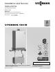
Installation and Service Instructions for use by heating contractor Vitodens 100-W WB1B Series Wall-Mounted, gas-fired condensing boiler with optional on demand hot water CombiPLUS Kit Heating input 37 to 118 MBH 10.8 to 34.5 kW VITODENS 100-W H IMPORTANT Vitodens 100-W, WB1B (with pre-installed coaxial vent pipe adaptor) and with CombiPLUS Kit installed. 5600 332 - 06 01/2015 Read and save these instructions for future reference.
Safety Vitodens 100-W, WB1B Installation & Service Safety, Installation and Warranty Requirements Please ensure that these instructions are read and understood before commencing installation. Failure to comply with the instructions listed below and details printed in this manual can cause product/property damage, severe personal injury, and/or loss of life. Ensure all requirements below are understood and fulfilled (including detailed information found in manual subsections).
Vitodens 100-W, WB1B Installation & Service Table of Contents 5600 332 - 06 Page Safety Safety, Installation and Warranty Requirements..............2 Important Regulatory and Installation Requirements........5 General Information About these Installation Instructions..............................7 Applicability. .............................................................8 Product Information.....................................................8 Mechanical Room. .....................................
Table of Contents Vitodens 100-W, WB1B Installation & Service Page Venting Connections Control Connections Start-up, Inspection and Maintenance 4 Installation Examples.................................................36 General.................................................................36 Clearances...........................................................36 Pressure drop of Vitodens 100-W.............................36 Typical system flow rates........................................
Safety Vitodens 100-W, WB1B Installation & Service Important Regulatory and Installation Requirements Codes The installation of this unit shall be in accordance with local codes or, in the absence of local codes, use CAN/ CSA-B149.1 or .2 Installation Codes for Gas Burning Appliances for Canada. For U.S. installations use the National Fuel Gas Code ANSI Z223.1. Always use latest editions of codes. In Canada all electrical wiring is to be done in accordance with the latest edition of CSA C22.
Safety Vitodens 100-W, WB1B Installation & Service Important Regulatory and Installation Requirements (continued) For installations on the Commonwealth of Massachusetts, the following modifications to NFPA-54 chapter 10 apply: Excerpt from 248 CMR 5-08: 2(a) For all side-wall horizontally vented gas fueled equipment installed in every dwelling, building or structure used in whole or in part for residential purposes, including those owned or operated by the Commonwealth and where the side-wall exhaust ve
Safety/ General Information Vitodens 100-W, WB1B Installation & Service Important Regulatory and Installation Requirements Working on the equipment The installation, adjustment, service, and maintenance of this boiler must be performed by a licensed professional heating contractor who is qualified and experienced in the installation, service, and maintenance of hot water boilers. There are no user serviceable parts on the boiler, burners, or control.
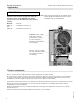
General Information Vitodens 100-W, WB1B Installation & Service Applicability IMPORTANT The boiler serial number must be provided when ordering replacement parts. Both the 16-digit serial number bar code label and the 12-digit ASME/NB serial number correlate to each other. Providing either serial number is sufficient. Model No. WB1B 26 and WB1B 35 Note: Check the boiler rating plate on the Vitodens 100-W, models WB1B-26 or WB1B-35 to ensure it states compatibility with the CombiPLUS kit. Serial No.
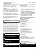
General Information Vitodens 100-W, WB1B Installation & Service Mechanical Room During the early stages of new home design, we recommend that proper consideration be given to constructing a separate mechanical room dedicated to gas- or oil-fired equipment including domestic hot water storage tanks. Installation area conditions The boiler must be located in a heated indoor space, near a floor drain, and as close as possible to the wall.
Dimensions Vitodens 100-W, WB1B Installation & Service Minimum Clearances Recommended minimum service clearances Note:The Vitodens 100-W boiler has passed the zero inches vent clearance to combustibles testing requirements dictated by the boiler Harmonized Standard ANSI Z21.13. CSA 4.9.2007 and therefore is listed for zero clearance to combustibles when vented with a single-wall special venting system (AL-29-4C material) or UL/ULC-listed CPVC gas vent material.
Dimensions Vitodens 100-W, WB1B Installation & Service Preparing the Connections Note: Use an approved pipe sealant or teflon tape when connecting the following installation fittings. Connections overview This section is an overview only! Refer to subsequent sections for detailed information on individual piping connections.
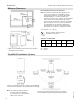
Dimensions Preparing the Connections Vitodens 100-W, WB1B Installation & Service (continued) Dimensions overview without bottom piping connections Front view Side view Top view Connections Vitodens 100-W, WB1B 26, 35 When preparing gas, water and electrical connections in the field, see section entitled “Wall Mounting” on page 15 of this manual for information regarding the installation of the wall mounting bracket. Legend Connections A Condensate drain, plastic hose Ø 0.
Dimensions Vitodens 100-W, WB1B Installation & Service Preparing the Connections (continued) CombiPLUS connections and piping connections Front view Side view Top view Legend A B A Boiler water supply, NPTM ¾” (male thread) B Boiler water return, NPTM ¾” (male thread) C System water supply, NPTM ¾” (male thread) C E F D D System water return, NPTM ¾” (male thread) E DHW, NPTM ½” (male thread) 5600 332 - 06 F DCW, NPTM ½” (male thread) Front view Shown is the distance between the boiler and C
Dimensions Preparing the Connections Vitodens 100-W, WB1B Installation & Service (continued) This section is an overview only! Refer to subsequent sections for detailed information on individual piping connections.
Dimensions Vitodens 100-W, WB1B Installation & Service Wall Mounting Boiler and CombiPLUS installation The Vitodens 100-W boiler and CombiPLUS can be wall-mounted on: - a brick/concrete wall - wood studs - metal studs Following are the installation instructions for the mounting bracket on each material. Skip to the installation instructions applicable to your installation requirements. Installation of mounting bracket on brick/concrete wall: 1.
Dimensions Vitodens 100-W, WB1B Installation & Service Wall Mounting (continued) Boiler mounting bracket and CombiPLUS installation Installation on wood studs Install mounting bracket and CombiPLUS on wood studs as per illustration. Drill 3/16” pilot holes to insert mounting bolts. Ensure that holes are located in the center of each wood stud. Secure with bolts to wooden studs as shown.
Dimensions/Connections Vitodens 100-W, WB1B Installation & Service Wall Mounting (continued) Mounting Vitodens 100-W boiler Note: Prior to installing the boiler, if a CombiPLUS kit is also required, verify that the minimum mounting clearances are met. 1. Loosen the screws at the bottom of the boiler; do not remove completely. 2. Remove the front panel. 3. Mount boiler onto the mounting bracket.
Connections Vitodens 100-W, WB1B Installation & Service Boiler Connections (continued) Proper piping practice 2 imperfect threads Use moderate amount of dope Support piping by proper suspension method. Piping must not rest on or be supported by boiler. Leave 2 threads bare Gas connection and piping 1. Make gas connection in accordance with codes CAN/CSA B149.1 or 2 in Canada. In the United States, use the National Fuel Gas Code ANSI Z223.1/ NFPA 54, as well as local codes where applicable. 2.
Connections Vitodens 100-W, WB1B Installation & Service Boiler Connections (continued) Gas connection and piping (continued) 1. Refer to current CAN/CSA B149.1 or 2 in Canada. In the United States, use the National Fuel Gas Code ANSI Z223.1/NFPA 54, as well as local codes for gas piping requirements and sizing. Pipe size to the boiler must be determined based on: - pipe length - number of fittings - maximum input requirements of all gas appliances in the residence.
Connections Boiler Connections Vitodens 100-W, WB1B Installation & Service (continued) Heating water connections 1. Thoroughly flush heating system (particularly before connecting the boiler to an existing system). 2. Connect boiler to the heating system. Max. operating pressure.......................3 bar (45 psig) Test pressure......................................4 bar (60 psig) IMPORTANT Damage resulting from pressure exceeding those values stated is not covered by Viessmann warranty.
Connections Vitodens 100-W, WB1B Installation & Service Boiler Connections (continued) Condensate connection The Vitodens 100-W boiler comes with a built-in condensate trap. An external trap is not required when connecting the field drain to flexible discharge tubing. Discharge tubing (field supplied) must be of 1” diameter. Use CPVC, PVC or other material approved by codes listed below. In the U.S. the drain pipe and fittings must conform to ANSI standards and ASTM D1785 or D2846.
Connections Vitodens 100-W, WB1B Installation & Service Safety Connections and Pressure Testing Installing safety devices on the boiler 1. Remove loosely pre-assembled combination pressure relief valve and drain valve assembly. 2. Apply sufficient amount of pipe sealant to both ends of all pipe fittings B, C, and E, and install onto tees D, F. 3. Install pressure relief valve A and tighten.
Connections Vitodens 100-W, WB1B Installation & Service Safety Connections and Pressure Testing Hot water temperature and system pressure (continued) Performing pressure test on the boiler The boiler must be leak tested before being placed in operation. Before boiler is connected to piping or electrical power supply, it must be hydrostatically pressure tested. 1. Cap supply and return connections (¾” NPT Male). 2.
Connections Vitodens 100-W, WB1B Installation & Service Preparing the CombiPLUS Connections 15c” (400) 1315/16” (355) 507/16” (1280) when using 7” flex pipe. 547/16” (1382) when using 12” flex pipe. 117/16” (291) when using 7” flex pipe. 157/16” (393) when using 12” flex pipe. 8c” (223) 1015/16” (265) 16” (406) 17” (431) 913/16” (249) 24 5600 332 -06 Note: The flex pipes must be bent due to the offset in the fittings between the boiler and the CombiPLUS.
Connections Vitodens 100-W, WB1B Installation & Service CombiPLUS Preparations for all Vitodens Installing the extension fitttings B and system connections D, E, F and G to the CombiPLUS A. 3. B 1. Using a Phillips screw driver, remove all four screws holding the CombiPLUS A cover and set aside. 2. Remove the cover by pulling straight out from the CombiPLUS A and set aside. 3.
Connections Vitodens 100-W, WB1B Installation & Service Additional CombiPLUS Preparations for Vitodens 100-W, WB1B-26 only The CombiPLUS A flow restrictor must be exchanged when used with the Vitodens 100-W, WB1B-26. 1. 1. Remove the two 4 mm hex head cap screws from the flow tube cap and set aside. Gently remove the flow tube cap by pulling straight up (ensure not to damage the gasket) and set aside.
Connections Vitodens 100-W, WB1B Installation & Service Mounting the CombiPLUS Prepare the wall and mount the CombiPLUS A using the supplied template and mounting hardware. 1. Pull the bottom of the boiler away from the wall approximately 1/2” (12 mm) and slide the top of the CombiPLUS mounting template T between the wall and the boiler. Release the boiler and allow the weight of the boiler to hold the template in place.
Connections Vitodens 100-W, WB1B Installation & Service Connecting the CombiPLUS Piping Connecting the CombiPLUS A using the supplied piping, adaptors and mounting hardware. N 1. Install the adaptors N to the tees at the bottom of the boiler. Install the flex pipes L or M to the adaptors N. Carefully form the flex pipes L or M to align with the extension fittings on the top of the CombiPLUS A. N 1.
Connections Vitodens 100-W, WB1B Installation & Service Connecting the CombiPLUS Wiring Connecting the CombiPLUS A wiring using the supplied control and pump cables. 1. Q R 1. Remove both standard knock-outs from the rear right side of the CombiPLUS A. Route the control cable Q through one knock-out and the pump cable R through the other. Note: There are optional knock-outs on the front left side of the CombiPLUS A (if required). Secure the cables inside the CombiPLUS A using the locknuts provided.
Connections Vitodens 100-W, WB1B Installation & Service Accessing the Boiler Controls Removing the boiler and power pump module covers to provide access to the power pump module. 1. Loosen the boiler housing captive screws (located at the bottom front of the boiler). Remove the cover by pulling straight out from the boiler and set aside. 2. Release and hold the boiler control locks (located on both sides of the boiler) and rotate forward and down. 3.
Connections Vitodens 100-W, WB1B Installation & Service Preparing the Boiler Power Pump Module Preparing the power pump module for connection to the CombiPLUS wiring. When handling static sensitive components, avoid damage caused by static discharge by following Electro-Static Discharge safety procedures. 1. Remove the jumper pin from terminal X8 (CombiPLUS) of the power pump module and discard. Jumper pin 2.
Connections Vitodens 100-W, WB1B Installation & Service Connecting the CombiPLUS Cables to the Power Pump Module of the Boiler Connecting the CombiPLUS cables to the power pump module. 1. Route the control cable Q through the fourth hole of the power pump module base and route the pump cable R through the second hole of the power pump module base. Secure the cables inside the power pump module using the locknuts provided. V U W 1. V 2. R W U Q 4. 2.
Connections Vitodens 100-W, WB1B Installation & Service Re-installing Covers Reinstalling the covers for the boiler, power pump module and the CombiPLUS A. 1. Align and install the cover of the power pump module and lock into place by rotating the four captive screws 90 degrees with a Phillips screw driver. 2. Rotate the boiler controls up and in. Ensure that the locking clips are engaged. 3. Install the boiler cover by inserting it straight on from the front. 4.
Connections Vitodens 100-W, WB1B Installation & Service Adding PRV and Label Installing the PRV P and tee O to the CombiPLUS A and label S to the boiler. Boiler Supply Boiler Return P O The DHW pressure relief valve is designed to relieve excessive pressure in the system, produced during domestic hot water heating. Model: Watts No. 3L Size: ¾” NPT Max. Operating Pressure: 150 psig Input Rating: 200 MBH A Heating Circuit Supply DHW Note: The system must be leak tested.
Vitodens 100-W, WB1B Installation & Service Connections Programming Programming the boiler control for operation with or without the CombiPLUS. Note: If an optional CombiPLUS is used, the boiler control must be programmed. Note: For additional programming refer to the boiler Operating, Installation and Service Instructions. 1. Lift flap and pull control unit cover down. All boiler controls are located behind the control unit cover. 1. 2. “ and “tr“ 2.
Connections Vitodens 100-W, WB1B Installation & Service Installation Examples General The schematics on the following pages are to be seen as guidelines only. They further do not display all system varieties, safety devices, or concepts possible. Specific system layouts may be further discussed with the local Viessmann sales representative office. Clearances A minimum of 2” (51 mm) circumferential clearance from non-insulated hot water pipes to combustible construction must be maintained.
Connections Vitodens 100-W, WB1B Installation & Service Installation Examples (continued) CombiPLUS built-in pump Grundfos UPS15-78 three speed heating circuit/DHW production pump for Vitodens 100 WB1B 26, 35 boilers (in the factory setting, the pump speed is preset to ‘speed three’) Head H (ft of wc) Speed Three Speed Two Speed One Flow Q (gpm) Performance chart courtesy of Grundfos Pump Model Rated voltage Rated current Capacitor Power consumption Grundfos UPS15-78 VAC 115 A max. 1.15 A min. 0.
Connections Vitodens 100-W, WB1B Installation & Service Installation Examples (continued) System Layout 1 Vitodens 100-W, WB1B 26, 35 with... - one heating circuit Legend AV Air vent PRV Pressure relief valve A B C D E F AV PVR Vitodens 100-W Room thermostat Heating circuit Heating circuit pump (field supplied) Expansion tank Pressure Activated By-Pass Note: Heating circuit C in the examples should be designed to 30ºF to 40ºF (16.7ºC to 22.2ºC).
Connections Vitodens 100-W, WB1B Installation & Service Installation Examples (continued) System Layout 2 Vitodens 100-W, WB1B 26, 35 with...
Connections Vitodens 100-W, WB1B Installation & Service Installation Examples (continued) System Layout 3 Vitodens 100-W, WB1B 26, 35 with...
Connections Vitodens 100-W, WB1B Installation & Service Installation Examples (continued) System Layout 4 Vitodens 100-W, WB1B 26, 35 with... - DHW storage tank - Low-loss header - one high-temperature heating circuit - one low-temperature heating circuit - Viessmann Vitotronic 050, HK1M controller OPTIONAL ROOM THERMOSTAT SEE NOTE 2 120V POWER SUPPLY RT ATS ST 120V POWER SUPPLY 4-7 GPM FLOW GRUNDFOSS UPS-15-58FC 3-SPEED CIRCULATOR OR EQUIVALENT RECOMMENDED max. 17.
Connections Vitodens 100-W, WB1B Installation & Service Installation Examples (continued) Wiring diagram for system layout 4 To boiler/burner control unit GC1 ROOM THERMOSTAT RT DHW Vitotronic 050, Model HK1M Digital Indoor/ Outdoor Heating Circuit Control Unit & Power Pump Module Vi.PN 7134627 See Installation Instruction specific to each control 1PH Power Pump Module Honeywell Aquastat L4008A1031 Vi.PN.
Vitodens 100-W, WB1B Installation & Service Installation Examples Connections (continued) System Layout 4 Installation of heating circuits: - radiator heating circuit (high temperature circuit) - underfloor heating circuit with 3-way mixing valve (low temperature circuit) - DHW production with the following flow conditions: The flow rate of the heating circuits is greater than the maximum possible water flow rate of the Vitodens 100 boiler. The use of a low-loss header is therefore recommended.
Connections Installation Examples Vitodens 100-W, WB1B Installation & Service (continued) Vitodens 100-W, WB1B 26, 35 with one heating circuit and the CombiPLUS Maximum Flow Rates Model WB1B t Output Btu/h 30ºF (17ºC) rise (GPM) 35ºF (19.5ºC) rise (GPM) 40ºF (22ºC) rise (GPM) 26 35 83,000 5.5 4.7 4.2 108,000 ---6.2 5.4 Note: The use of a low-loss header is recommended if the water flow rate is less than 1.7 GPM (400 L/h) or more than 6.2 GPM (1400 L/h).
Connections Vitodens 100-W, WB1B Installation & Service Installation Examples (continued) Vitodens 100-W, WB1B 10-26, 10-35 with... CombiPLUS Kit low-loss header one heating circuit Note: The use of a low-loss header is recommended if the water flow rate is less than 1.7 GPM (400 L/h) or more than 6.2 GPM (1400 L/h). The low-loss header is available as accessory part. Maximum Flow Rates Model WB1B t Output Btu/h 30ºF (17ºC) rise (GPM) 35ºF (19.5ºC) rise (GPM) 40ºF (22ºC) rise (GPM) 26 35 83,000 5.
Connections Installation Examples Vitodens 100-W, WB1B Installation & Service (continued) Vitodens 100-W, WB1B 10-26, 10-35 with CombiPLUS and one heating circuit without LLH Note: The use of a low-loss header is recommended if the water flow rate is less than 1.7 GPM (400 L/h) or more than 6.2 GPM (1400 L/h). The low-loss header is available as an accessory part. Maximum Flow Rates Model WB1B t Output Btu/h 30ºF (17ºC) rise (GPM) 35ºF (19.5ºC) rise (GPM) 40ºF (22ºC) rise (GPM) 26 35 83,000 5.5 4.
Connections Vitodens 100-W, WB1B Installation & Service Installation Examples (continued) Boiler in heating/cooling application Legend A Heating/Cooling unit B Spring-loaded flow check valve C Circulation pump D Expansion tank E Water chiller F Boiler circuit pump (field supplied) IMPORTANT Viessmann strongly suggests that the valves pictured above be labelled “v1” and “v2”.
Connections Installation Examples Vitodens 100-W, WB1B Installation & Service (continued) Boiler with low water cut-off (remote-mounted, field supplied) Hi-Vent Hi-Vent A low water cut-off may be required by local codes. If boiler is installed above radiation level, a low water cut-off device of approved type (field supplied) must be installed in all instances at the highest point of the piping system. Do not install an isolation valve between boiler and low water cut-off.
Connections Vitodens 100-W, WB1B Installation & Service Installation Examples (continued) Accessories for the Vitodens 100-W Neutralization Unit for Single-Boiler Applications with neutralizing granulate for Vitodens 100-W, WB1B 26, 35 Part No. 7134 231 Vprimary Vbypass Vsecondary Low-Loss Header - Type 80/50, Part No. 7134 791 [max. flow rate 17.6 GPM (4 m3/h)] - Type 120/80, Part No. 7134 792 [max. flow rate 35.
Venting / Control Connections Vitodens 100-W, WB1B Installation & Service Venting Connection CAUTION Under certain climatic conditions some building materials may be affected by flue products expelled in close proximity to unprotected surfaces. Sealing or shielding of the exposed surfaces with a corrosion resistant material (e.g. aluminum sheeting) may be required to prevent staining or deterioration.
Control Connections Vitodens 100-W, WB1B Installation & Service Electrical Connections (continued) Electrical connections to the power pump module (room thermostat and DHW) IMPORTANT Remove short factory test leads from terminal L, N and Ground before connecting main power supply to boiler A. Note: Boilers are factory shipped with a wiring diagram (11”x17” sheet inside a pouch) attached to the inside of the front cover.
Control Connections Electrical Connections Vitodens 100-W, WB1B Installation & Service (continued) Closing the power pump module and reinstalling the control unit 1. Reinstall power pump module cover plate. 2. Install control cover (if previously removed). 3. Flip control upward and lock into position. CAUTION Electrical cables may become damaged if in contact with hot components.
Start-up, Inspection and Maintenance Vitodens 100-W, WB1B Installation & Service Necessary Tools Testing/analysis equipment (use only calibrated equipment) Multimeter to measure 0 - 12A, 120V and resistances Flue gas analyzer to measure % CO2 or O2 (i.e. Bacharach fluid samplers or suitable electronic flue gas analyzer) Manometer to measure gas pressure 0 to 11 “w.c. (accurately) and up to 28 “w.c.
Start-up, Inspection and Maintenance Vitodens 100-W, WB1B Installation & Service Overview of Boiler Components Fig.
Vitodens 100-W, WB1B Installation & Service Start-up, Inspection and Maintenance Overview of CombiPLUS Components Fig.
Start-up, Inspection and Maintenance Vitodens 100-W, WB1B Installation & Service Procedure Overview Start-up steps Inspection steps Maintenance steps S S S S S I I I I I I I I I I I I I I I I I I I 56 M M M M M M M 1. Fill and vent the heating system ......................................................................................57 2. Check power supply connection.......................................................................................58 3.
Start-up, Inspection and Maintenance Vitodens 100-W, WB1B Installation & Service Steps 1. Filling and bleeding heating system Start-up 1. Open system isolation valves (if installed). Note: Before filling the heating system with water, check that all necessary flow check valves are installed. A B CAUTION Unsuitable fill water increases the level of deposits and corrosion, and may lead to damage to the equipment. Thoroughly flush the entire heating system prior to filling with water.
Start-up, Inspection and Maintenance Steps Vitodens 100-W, WB1B Installation & Service (continued) 1. Fill and vent heating system (continued) Start-up 5. Check system pressure. 6. Ensure proper / adequate fuel supply exists. Open gas shutoff valve. Max. boiler operating pressure.......................45 psig Min. boiler operating pressure...............14 to 23 psig Pressure relief valve.....................................30 psig 2.
Vitodens 100-W, WB1B Installation & Service Steps Start-up, Inspection and Maintenance (continued) Start-up and Maintenance 3. Select appropriate gas type (continued) To verify the fuel type “ and “tr“ 1. Simultaneously turn selector dial “ to their center position as shown. “SERV" appears in the display. (To do the following step, “SERV" must still be shown in the display). 2. Turn selector dial “tr” counter clockwise to the “O” position within 2 seconds as shown.
Start-up, Inspection and Maintenance Steps Vitodens 100-W, WB1B Installation & Service (continued) Start-up and Maintenance 4. Measure static pressure and running pressure (continued) 8. All measurements must be made under high-fire conditions. Measuring running gas supply pressure, using test nipple A Note: Use suitable measuring instruments calibrated with a minimum resolution of 0.04 “w.c. for measuring the running pressure.
Vitodens 100-W, WB1B Installation & Service Steps Start-up, Inspection and Maintenance (continued) Start-up and Maintenance 5. How the Vitodens 100-W boiler operates... The Vitodens 100-W boiler uses a premix combustion system, which is designed to deliver a measured air-gas mixture to the burner for complete combustion. The gas is injected upstream of the blower. The burner and heat exchanger are part of a forced-draft design.
Start-up, Inspection and Maintenance Steps Vitodens 100-W, WB1B Installation & Service (continued) Start-up and Maintenance 6. Relay tests (burner tests) The Vitodens 100-W boiler is factory preset for operation with natural gas. It is recommended that a CO2 check be performed at the boiler vent pipe adaptor as part of the initial start-up/maintenance procedure. For high altitude operation above 5,000 ft (1,500 m), refer to page 64 first. For conversion to propane, see the separate instructions.
Vitodens 100-W, WB1B Installation & Service Steps Start-up, Inspection and Maintenance (continued) 6. Relay tests (burner tests) (continued) Start-up and Maintenance Note: During the relay test (if required) the selector dial “tr” position can limit the boiler input according to the following table; Dial setting Input setting Display flashing 1 & below low fire < between 1 & 6 between low & high fire <<< 6 & above <<<< high fire < 2. Check the flue gas CO2 content.
Start-up, Inspection and Maintenance Steps Vitodens 100-W, WB1B Installation & Service (continued) Start-up and Maintenance 7. High altitude setting Note: When the boiler is initially turned on, a selfdiagnostic check is initiated. Wait until the temperature display is stabilized and the boiler’s actual temperature is displayed. 1. Simultaneously turn selector dials “ ” and “tr” to their center position. “SERV” appears in the display.
Vitodens 100-W, WB1B Installation & Service Steps Start-up, Inspection and Maintenance (continued) Start-up and Maintenance 8. Set maximum heating input - The maximum input (or output) for heating operation can be limited (does not affect DHW heating). The limit is set via the modulation range. The maximum adjustable heating input (or output) may be limited by programming. 1. Start up the boiler. Control range 2.
Start-up, Inspection and Maintenance Steps Vitodens 100-W, WB1B Installation & Service (continued) Start-up and Maintenance 9. Clock natural gas meter Clock natural gas meter to verify input IMPORTANT A boiler under fired by 5% is still acceptable. Do not over fire the boiler. CAUTION Always contact your gas utility to obtain the correct heating value before clocking the meter. 1.
Start-up, Inspection and Maintenance Vitodens 100-W, WB1B Installation & Service Steps (continued) Start-up and Maintenance 12. Check venting system for leaks (circular air gap measurement) For sealed combustion, coaxial vent only Viessmann strongly recommends that the heating contractor perform a simplified leak test during boiler start-up. For this purpose it is sufficient to measure the CO2 concentration of the combustion air in the coaxial gap of the air intake pipe.
Start-up, Inspection and Maintenance Steps Vitodens 100-W, WB1B Installation & Service (continued) Maintenance 14. Remove burner 1. Switch the burner OFF (shut off main service switch). 2. Shut off the gas supply. 3. Pull power cables from fan motor A, gas valve B and electrode block C. 4. Pull the Venturi extension D from the fan. Start-up and Maintenance CAUTION To avoid damage to the burner, do not lay burner on its cylindrical burner tube.
Start-up, Inspection and Maintenance Vitodens 100-W, WB1B Installation & Service Steps (continued) Maintenance Start-up and Maintenance 16. Check and adjust ignition and ionization electrodes 1. Check ignition and ionization electrode for wear, contamination or warping. 2. Clean electrodes with a small brush or emery paper. 3. Check clearances. If clearances are not satisfactory or the electrodes are damaged, replace electrode block and gasket and align.
Start-up, Inspection and Maintenance Steps Vitodens 100-W, WB1B Installation & Service (continued) Maintenance 18. Check neutralization unit (if applicable) Accessory 1. Check the pH value of the condensate with a pH measuring strip. If the pH value is less than 6.5, replace granulate. 2. If contaminated: Rinse neutralization unit with tap water. 3. Add granulate as marked on the cartridge. IMPORTANT pH measuring strip is field supplied.
Vitodens 100-W, WB1B Installation & Service Steps Start-up, Inspection and Maintenance (continued) Start-up and Maintenance 20. Check diaphragm expansion tank and system pressure Perform check on the system when cold. 1. Drain boiler/system and reduce pressure until the manometer reading is “0”. Start-up and Maintenance 2. If the nitrogen pressure of the pre-charged expansion tank is less than the static pressure of the system, inflate membrane pressure to slightly exceed pressure of system.
Start-up, Inspection and Maintenance Steps Vitodens 100-W, WB1B Installation & Service (continued) Start-up and Maintenance 22. Check gas pipes and fittings for leaks WARNING The gas supply piping must be leak tested before placing the boiler in operation. CAUTION Ensure all joints of gas line are pressure tight and that gas valves do not leak when under normal operating pressure (use approved leak detection liquid). Do not use open flame. Start-up and Maintenance 23. Reinstall burner 1.
Vitodens 100-W, WB1B Installation & Service Troubleshooting Troubleshooting Steps Diagnosis 1. Establish fault message or diagnose behavior of system. 2. Look for corresponding cause of fault in the diagnostics table. 3. Find corrective measures in the table. 4. Perform corrective measures (page 74 to 76). Note: See page 54 and 55 for an overview of controls, indicators and system components.
Troubleshooting Vitodens 100-W, WB1B Installation & Service Diagnosis Sequence of operation and potential faults during each start-up cycle Corrective action Call for heat by control (boiler water set-point temperature is 9ºF (5ºC) above current boiler water temperature). Increase boiler water set-point temperature and ensure that there is heat demand. yes Water flow switch activates plug 33. Check water flow switch. Replace if necessary (min. flow 1.8 USG/m (400 L/h).
Troubleshooting Vitodens 100-W, WB1B Installation & Service Diagnosis (continued) Faults are indicated by a flashing fault code with fault code symbol “U” on the display. For fault code explanations see the following table.
Troubleshooting Diagnosis Vitodens 100-W, WB1B Installation & Service (continued) Diagnostics table: Faults with fault display on control unit (continued) Fault code in display window System characteristics*1 Cause Corrective measures f1 Burner in fault mode Maximum flue gas temperature exceeded Check the flue gas system. Reset control. f2 Burner in fault mode Fixed high limit tripped Check the heating system water level. Check the circulation pump. Bleed the system.
Troubleshooting Vitodens 100-W, WB1B Installation & Service Boiler Connection Remove front panel 1. Loosen the screws at the bottom of the boiler; do not remove completely. 2. Remove the front panel. Start-up and Maintenance Check boiler temperature sensor 1. Disconnect cables from boiler temperature sensor A. 2. Measure resistance of the boiler temperature sensor and compare with resistance/boiler water temperature curve shown. 5600 332 - 06 Resistance in K 3.
Troubleshooting Boiler Connection Vitodens 100-W, WB1B Installation & Service (continued) Check outdoor temperature sensor 1. Disconnect cables from outdoor sensor. 2. Measure resistance of the outdoor sensor and compare with resistance / outdoor sensor curve shown below. 3. If the value measured differs significantly, replace the sensor. In weather-compensated mode (optional), the boiler water temperature is regulated subject to the outside temperature.
Troubleshooting Vitodens 100-W, WB1B Installation & Service Boiler Connection (continued) Determining the boiler set-point Boiler water or supply temperature Room dependent control: Outdoor temperature sensor not connected With no outdoor sensor installed, the “tr” dial will provide a constant temperature set-point for the boiler based on the dial position selected. Setting the dial between 1 and 6 will provide a set-point value of 81ºF to 178ºF (27ºC to 81ºC) respectively.
Troubleshooting Boiler Connection Vitodens 100-W, WB1B Installation & Service (continued) Check fixed high limit If the burner control unit cannot be reset after a fault shutdown (F2), even though the boiler water temperature is below approx. 203°F (95°C), check the fixed high limit. 1. Pull the leads from fixed high limit A. 2. Check the continuity of the fixed high limit with a multimeter. 3. Remove faulty fixed high limit. 4. Coat the replacement fixed high limit with heat conducting paste and install.
Troubleshooting Vitodens 100-W, WB1B Installation & Service Boiler Connection (continued) Check fuses Control unit fuse 1. Switch off main power supply. 2. Flip down control unit. 3. Remove cover A. 4. Check fuse F4 T 2.5A (slow blow). Replacements fuses are available from Viessmann in packs of 10 (Part No. 7404 396). Start-up and Maintenance Start-up and Maintenance Power pump module fuse 1. Switch off main power supply. 2. Flip down and remove control unit A. Also refer to pages 50 and 52. 3.
Troubleshooting Vitodens 100-W, WB1B Installation & Service CombiPLUS Connection Check outlet temperature sensor 1. Pull the leads from outlet temperature sensor A. 2. Check the sensor resistance and compare it with the curve. Resistance in K 3. Replace the sensor in case of severe deviation. Temperature Note: Water can leak when replacing the outlet temperature sensor. Shut off the cold water supply. Drain the DHW line and the plate type heat exchanger (DHW side). Replacing the flow limiter 1.
Vitodens 100-W, WB1B Installation & Service CombiPLUS Connection Troubleshooting (continued) Checking or replacing the plate type heat exchanger 1. Shut off and drain the boiler on the heating water and the DHW side. 2. Disconnect diverting valve motor connection 3. Push the three-way drive A slightly upwards. 4. Turn the three-way valve B with drive A 1/8 turn counterclockwise and remove. 5. Remove two screws C from the plate-type heat exchanger and remove the plate-type heat exchanger D with gaskets.
Additional Information Vitodens 100-W, WB1B Installation & Service Electrical Connections to the Terminal Strip for Accessories Follow the installation instructions of field supplied operating controls. Boiler reset module (0-10V controller) OT-Devices Boiler control What is OpenTherm? The OpenTherm (OT) protocol is a point-to-point communication system, which connects a boiler with a room controller or other devices.
Additional Information Vitodens 100-W, WB1B Installation & Service Technical Data Call for heat priority logic table The Vitodens 100-W, WB1B boiler has several operating control options. The following table provides the priority levels of each of the different operating controllers.
Additional Information Technical Data Vitodens 100-W, WB1B Installation & Service (continued) Rated voltage:.................................................120VAC Rated frequency: .................................................60 Hz Rated current:...................................................6.0 A~ Setting of adjustable electronic high limit:.....176ºF (80ºC) Max. ambient temperature - at operation:.................32º to 104ºF (0º to +40ºC) - when storing and transporting:...........
Additional Information Vitodens 100-W, WB1B Installation & Service Technical Data (continued) Standard heating boiler Boiler Model Model No. WB1B 26 WB1B 35 inches mm inches mm inches mm 14d 360 15c 400 28b 725 14d 360 15c 400 28b 725 NPTF (female)” c” c” ºF (ºC) ºF (ºC) 127 (53) 90 (32) 131 (55) 90 (32) ºF (ºC) 167 (75) 172 (78) lbs/h kg/h lbs/h kg/h 79.2 36.0 33.0 15.0 100.1 45.5 33.0 15.0 Pa mbar 100 1.0 100 1.0 ºF (ºC) 230 (110) 230 (110) USG/day L/day 1.95-2.3 8-9 2.5-2.
Additional Information Vitodens 100-W, WB1B Installation & Service Technical Data (continued) Integrated with the Boiler Model No. WB1B 26 WB1B 35 DHW supply temperature ºF (ºC) 140 (60) 140 (60) Continuous draw rate 1 with DCW temp.
Additional Information Vitodens 100-W, WB1B Installation & Service fire 8: Bu c o rne r ntr in olle ope r a ra t i c ti v e on: 9: Po s te s t pu rge t sp ee d 10 Co : va mb clo lve pinatio ser roo n g te s f o a s f t O: Sta nd - by low n ion tim e 5: Ign tim ition ing / s a fe ty 6: Fla tim me s ta b e iliz a ti o 7: Fo rc ed nit 4: Pre -ig y d- b O: Sta n 1: Sta te s nd- s t (s till afe sta ty tus ch ec 2: k) Ma x i RP mu M ve m blo rifi ca wer tio n 3: Pre - pu rge Burner Program Sequence of O
Additional Information Vitodens 100-W, WB1B Installation & Service Burner Program Sequence of Operation (continued) Phase 0: Stand by Complete shutdown until the next call for heat. In this phase both the combination gas valve and the blower are not energized. Phase 7: Forced low-fire The controller will go into low-fire until required modulation signal (high-low) is processed (e.g. boiler actual water temperature).
Vitodens 100-W, WB1B Installation & Service Additional Information 5600 332 - 06 Wiring Diagram - Natural gas / Propane 91
Additional Information Vitodens 100-W, WB1B Installation & Service Service Function Overview Addition / Condition Filling - Relay Test - Activation Sequence 1. 2. 3. Selector Dial Position / Selection Selector Dial Position / Selection Selector Dial Position / Selection r Selector Dial Left r Control Range - - r Selector Dial Right r Control Range r Position 1 And Below → Minimum Load Between 1 And 6 → Selected Inputs Position 6 And Above → Full Input Red. Max.
Vitodens 100-W, WB1B Installation & Service Additional Information Parts List Model No. WB1B 26 WB1B 35 Serial No. 7374861 7374862 WB1B 26c WB1B 35c 7457960 7457961 Ordering Replacement Parts: Please provide Model and Serial Number from rating plate A when ordering replacement parts. Order replacement components from your Viessmann distributor.
Additional Information Parts List Vitodens 100-W, WB1B Installation & Service (continued) Parts 001 Heat exchanger assembly, ASME 002 Heat exchanger connection pipe (supply) 003 Heat exchanger connection pipe (return) 004 Spring clips (set) 006 Fastener set (return pipe) 009 Vent pipe adaptor 010 P-Trap 011 Gasket for flue gases 012 Air intake cover 013 Air intake cap 014 Test port cap (set of 2) 015 Wall-mount bracket 016 Combustion chamber refractory Start-up and Maintenance 017 Condensate pipe 018 Co
Vitodens 100-W, WB1B Installation & Service Additional Information Parts List (continued) Parts 008 080 081 085 086 Pressure gage (PSI) Control console Control console cover Fuse, 2.5A/250V (pkg of 10) (for control console 080) Power/Pump control module Other Parts (not illustrated) 089 Fuse, 6.3A/250V (pkg of 10) (for 086 Power/pump control module) 063 Control bracket 101 Wiring harness, X20 102 Connecting cable No. 35 for gas valve 103 Connecting cable No.
Additional Information Parts List Vitodens 100-W, WB1B Installation & Service (continued) CombiPLUS Kit Part No. 7459 305 Model No. WB1B 26c WB1B 35c Serial No. 7457960 7457961 Ordering Replacement Parts: Please provide Model and Serial Number *1 when ordering replacement parts. ur Order replacement components from your Viessmann distributor.
Vitodens 100-W, WB1B Installation & Service Parts List Additional Information (continued) Parts 323 Accessory pack, plugs, clips (340 and 344) 330 Replacement powerhead, UPS15-78, 120/1/60 331 Plate heat exchanger, 20 plates 332 Gasket set, PWT 333 Step motor, linear 334 Flow sensor 335 Air vent 337 Bypass cartridge 339 Clip d=8 (set of 5) 340 Clip d=10 (set of 5) 342 Clip d=16 (set of 5) 344 special (set of 5) Start-upClip and SIV Maintenance 348 Expansion pipe 383 Sensor #3 boiler 390 Flow regulator,
by: max. 14 “w.c. Setpoint value vol.-% at upper end of rated input range (high-fire) vol.-% at upper end of rated input range (high-fire) Never exceed 50 ppm air-free Never exceed 200 ppm air-free ppm ppm at lower end of rated input range at upper end of rated input range Carbon monoxide content CO vol.-% at lower end of rated input range (low-fire) Oxygen content O2 vol.-% at lower end of rated input range (low-fire) Carbon dioxide content CO2 10-14 “w.c.
Additional Information Vitodens 100-W, WB1B Installation & Service Lighting and Operating Instructions FOR YOUR SAFETY READ BEFORE OPERATING W A R N I N G: If you do not follow these instructions exactly, a fire or explosion may result causing property damage, personal injury or loss of life. A. This appliance does not have a pilot. It is equipped with an ignition device which automatically lights the burner. Do not try to light the burner by hand. B.
5600 332 - 06 Technical information subject to change without notice. Printed on environmentally friendly (recycled and recyclable) paper.