Vitoden 200-W installation 4/9/07 7:27 pm Page 1 Installation Instructions For Corgi Registered Heating Engineers Vitodens 200-W Type WB2B, 4.8 to 35.
Vitoden 200-W installation 4/9/07 7:27 pm Page 2 Index Product information . . . . . . . . . . . . . . . . . . . . . . . . . . . . . . . . . . . . . . . . . . . . . . . . . . . . . 4 Safety instructions . . . . . . . . . . . . . . . . . . . . . . . . . . . . . . . . . . . . . . . . . . . . . . . . . . . . . . . 5 Technical specification . . . . . . . . . . . . . . . . . . . . . . . . . . . . . . . . . . . . . . . . . . . . . . . . . . . 7 Appliance dimensions/connections . . . . . . . . . . . . . . . .
Vitoden 200-W installation 4/9/07 7:27 pm Page 3 Index Electrical connections . . . . . . . . . . . . . . . . . . . . . . . . . . . . . . . . . . . . . . . . . . . . . . . . . . . 46 Combination boiler . . . . . . . . . . . . . . . . . . . . . . . . . . . . . . . . . . . . . . . . . . . . . . . . . . . . . . . . . 47 System boiler - Separate heating and DHW circuits (4 pipes) . . . . . . . . . . . . . . . . . . . . . . . 48 System boiler - Calling up code 2 . . . . . . . . . . . . . . . . . . . . . . .
Vitoden 200-W installation 4/9/07 7:27 pm Page 4 Product information Vitodens 200-W Type WB2B, 4.8 to 35.0 kW Set up for operation with natural gas.
Vitoden 200-W installation 4/9/07 7:27 pm Page 5 Safety instructions Please follow these safety instructions closely to prevent the risk of accidents and material damage. Safety instructions explained If you notice a smell of gas Danger Danger This symbol warns against the risk of injury. Escaping gas can cause explosions which may lead to serious injury. Please note This symbol warns against the risk of material damage and environmental pollution.
Vitoden 200-W installation 4/9/07 7:27 pm Page 6 Safety instructions (cont.) • Close the main gas shut-off valve and safeguard against unauthorised reconnection. • Isolate the system from the electricity power supply, check that it is no longer ‘live’ and safeguard the electricity supply against unauthorised reconnection. Please note Electronic modules can be damaged by electro-staticdischarges.
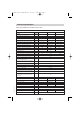
Vitoden 200-W installation 23/9/07 8:26 pm Page 7 Technical Specification General Specifications and Performance Data. Vitodens 200-W WB2B Appliance Mode Combi 26 kW Combi 30 kW Combi 35 kW 8.8 to 35.0 Unit Rated Central heating Output Tf/Tr 50/30 ºC (condensing) KW 6.5 to 26.0 8.8 to 30.0 Tf/Tr 80/60 ºC (non condensing) KW 5.9 to 24.1 7.9 to 27.8 7.9 to 32.2 Rated Central Heating Input (net) KW 6.2 to 24.7 8.3 to 28.5 8.3 to 33.0 Rated Central Heating Input (gross) KW 6.9 to 27.
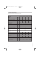
Vitoden 200-W installation 4/9/07 7:27 pm Page 8 Technical Specification General Specifications and Performance Data. Vitodens 200-W WB2B Appliance Mode System 19 kW System 26 kW System 30 kW System 35 kW 8.8 to 35.0 Unit Rated Central Heating Output Tf/Tr 50/30 ºC (condensing) KW 4.8 to 19.0 6.5 to 26.0 8.8 to 30.0 Tf/Tr 80/60 ºC (non condensing) KW 4.3 to 17.5 5.9 to 24.1 7.9 to 27.8 7.9 to 32.2 Rated Central Heating Input (net) KW 4.5 to 17.9 6.2 to 24.7 8.3 to 28.5 8.3 to 33.
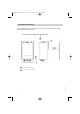
Vitoden 200-W installation 4/9/07 7:27 pm Page 9 Appliance dimensions/connections A Heating flow Rp 3/4" to 22mm Cu B DHW Rp 1/2" (combi boiler) to 15mm Cu Cylinder flow G 3/4" (boiler) to 15mm Cu 5350 485 GB 08/2007 C Gas Connection 1/2" to 15mm Cu D Cold water Rp 1/2" (combi boiler) to 15mm Cu Cylinder return G 3/4" (boiler) to |15mm Cu E Heating return Rp 3/4" to 22mm Cu F Fill & drain valve K Condensate discharge pipe 9
Vitoden 200-W installation 4/9/07 7:27 pm Page 10 Installation clearances 10 A Behind a cupboard door. B Space required for servicing. 5350 485 GB 08/2007 The following minimum clearances (mm) must be maintained for installing and maintaining the appliance.
Vitoden 200-W installation 4/9/07 7:27 pm Page 11 Sectional diagram 5350 485 GB 08/2007 Combination boiler illustrated 11
Vitoden 200-W installation 4/9/07 7:27 pm Page 12 Installation requirements Statutory requirements The appliance is suitable only for installation in GB and IE and should be installed in accordance with the rules in force. In GB, a corgi Registered Installer must carry out the installation.
Vitoden 200-W installation 4/9/07 7:27 pm Page 13 Flue terminal position • If the appliance is to be installed in a room containing a bath or shower, any electrical switch or control utilising mains electricity must be so situated that it cannot be touched by a person using the bath or shower. Attention is drawn to the requirements of BS 7671 (the current I.E.E Wiring Regulations) and in Scotland the electrical provisions of the Building Regulations applicable in Scotland.
Vitoden 200-W installation 4/9/07 7:27 pm Page 14 Flue terminal position (cont.
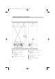
Vitoden 200-W installation 4/9/07 7:27 pm Page 15 Flue terminal position (cont.) Position From adjacent wall 300mm P From adjacent opening window 1000mm Q From another terminal 600mm R Minimum height 300mm Flue Terminal Location Detailed recommendations for flue installation are given in BS 5440:1. The following notes are for general guidance. • The boiler must be installed so that the terminal is exposed to external air.
Vitoden 200-W installation 4/9/07 7:27 pm Page 16 Flue system Flue gas temperature protection Installation notes The flue pipes are approved for flue gas temperatures up to 120 ºC. The interior design of Viessmann condensing boilers ensures that the maximum permissible flue gas temperature will not be exceeded. • Keep the flue gas path as short as possible and with the smallest possible number of bends. • Check the seating of the gaskets in all couplings. • Only use the special gaskets supplied.
Vitoden 200-W installation 4/9/07 7:27 pm Page 17 Flue system (cont.) Concentric Vertical Flue System The vertical flue kit option with extensions may be used for up to 10m total flue length. Before commencing the installation refer to diagram below to determine which optional extension kits are required, if any. An extra 87° elbow can be used but this reduces the maximum permissible length by 1m. An extra 45° elbow can be used but this reduces the maximum permissible length by 0.5m.
Vitoden 200-W installation 4/9/07 7:27 pm Page 18 Flue system (cont.
Vitoden 200-W installation 4/9/07 7:27 pm Page 19 Plume kit installation instructions The plume kit enables the relocation of the flue outlet of a standard horizontal flue system to another position and is available as an optional extra, please contact your supplier for further information. Routing options 5350 485 GB 08/2007 A Plume kit standard delivery 2m max length Ensure the max. length of the entire balanced flue system is not exceeded. The max.
Vitoden 200-W installation 4/9/07 7:27 pm Page 20 Fitting the plume kit 1. Unhook the external wall terminal of the flue at the external pipe and extract the flue with the end piece and the wall bezel. 2. Push the gasket and flue bend into the connector. 20 5350 485 GB 08/2007 3. Push the flue bend with the connector into the replacement pipe of the external wall terminal (transparent, 583mm long).
Vitoden 200-W installation 4/9/07 7:27 pm Page 21 Fitting the plume kit (cont.) 4. Push the replacement pipe with the connector and flue bend into the inner flue duct and secure with the screws supplied. 5350 485 GB 08/2007 5. Refit the wall bezel.
Vitoden 200-W installation 4/9/07 7:27 pm Page 22 Fitting the plume kit (cont.) 6. Fit the flue pipes and bends in accordance with the selected installation method and secure with the fixing clamps supplied. 7. Insert the rodent protection grill into the uppermost bend. Detailed recommendations for air supply are given in BS 5440:2. Please see additional notes below. 22 • It is not necessary to have a purpose provided air vent in the room or internal space in which the appliance is installed.
Vitoden 200-W installation 4/9/07 7:27 pm Page 23 Hydraulic connections Heating System (typical system designs) • The Vitodens 200-W is designed for connection to sealed central heating water systems only. • A sealed system must only be filled by a competent person. Combination boiler Note The boiler incorporates an internal bypass to ensure adequate water flow. Certain thermostatic radiator valve manufacturers may require that a bypass valve is fitted in addition to the integral by pass.
Vitoden 200-W installation 4/9/07 7:27 pm Page 24 Hydraulic connections Hydraulic circuits Combination boiler Boiler E B Heat exchanger F DHW outlet C Circulation pump G Cold water inlet D Three port diverter valve H Heating circuit Plate-type heat exchanger 5350 485 GB 08/2007 24 A
Vitoden 200-W installation 4/9/07 7:27 pm Page 25 Hydraulic connections System boiler using separate connections for DHW Cylinder & heating circuits (4 pipes) G A DHW cylinder B C D Circulation pump G E Three port diverter valve Boiler F Heating circuit Heat exchanger G DHW Circuit 5350 485 GB 08/2007 Note • The flow and return pipes to the cylinder can be connected either way round, however the optimum method would be to connect the flow pipe to the bottom connection of the cylinder •
Vitoden 200-W installation 4/9/07 7:27 pm Page 26 Hydraulic connections Weather compensated control instructions are supplied with the replacement controller and outside sensor kit. 26 A DHW cylinder E Three port diverter valve B C Boiler F Heating circuit Heat exchanger G D Circulation pump DHW circuit capped off 5350 485 GB 08/2007 System boiler when connected to Y or S plan systems (2 pipes).
Vitoden 200-W installation 4/9/07 7:27 pm Page 27 Gas and electric supply Gas supply • The Gas Supply should be checked at the installation planning stage in order to establish the availability of an adequate supply of gas. • The governor at the meter must give a constant outlet pressure of 21 mbar +/- 1mbar when the appliance is running. • A gas meter can only be connected by the gas supplier or their contractor. • The gas supply line should be purged.
Vitoden 200-W installation 4/9/07 7:27 pm Page 28 Electrical connections Electrical Connections Both combination and system boilers require a permanent live 240V supply. Combination boiler: Room temperature control is achieved by connecting a switched live 240V supply to the boiler. System boiler: For Y & S Plan systems a switched live 240V supply is required to be connected to the boiler. A Viessmann cylinder sensor is a thermistor and is connected directly to the boiler.
Vitoden 200-W installation 4/9/07 7:27 pm Page 29 Constant temperature control unit Control and display elements A Pressure gauge E User interface B Fault display (red) F ON/OFF switch C ON indicator (green) D Reset button Heating mode 5350 485 GB 08/2007 The selected set boiler water temperature will be maintained when a demand is created by the room thermostat and the heating programme is set to DHW and central heating .
Vitoden 200-W installation 4/9/07 7:27 pm Page 30 Constant temperature control unit (cont.) DHW heating with gas fired combi boilers If the flow switch detects that hot water is being drawn (>3 l/min) then the burner, circulation pump and 3-way valve are switched on or changed over. The burner modulates according to the DHW outlet temperature (max. 57ºC) and is limited by the temperature limiter (82ºC) on the primary side.
Vitoden 200-W installation 4/9/07 7:27 pm Page 31 Constant temperature control unit A Heating programmes ON/OFF H CH temperature B Info function K DHW time programme Clock/date setting Factory default setting L D Reset M Central heating time programme E Value adjustment F DHW temperature G Service function (only for qualified personnel) 5350 485 GB 08/2007 C N Party function (CH override) Please read the user manual for how to use the constant temperature control unit (Vitotronic
Vitoden 200-W installation 4/9/07 7:27 pm Page 32 Hydraulic components in the boiler Pump Pressure drop in mbar The following figure shows the pump head that is available in excess of the hydraulic resistance of the appliance.
Vitoden 200-W installation 4/9/07 7:27 pm Page 33 Installation of boiler Unpacking the appliance The appliance is supplied in 2 separate packages plus any optional flue packages. Check the availability and contents of each package before commencing the installation.
Vitoden 200-W installation 4/9/07 7:27 pm Page 34 Preparing the connections Note For dimensions for on-site preparations of the gas and water connections see “Overall Appliance Dimensions“ on page 9 1. Prepare the hydraulic connections. 3. Prepare gas connection to BS 6891 2. Clean and flush the heating system to BS 7593. Use only the following approved additives. 4. Prepare the electrical connections • Mains cable: H05V2V2-F 3 G 0.75 mm2, 230 V~, 50 Hz.
Vitoden 200-W installation 4/9/07 7:27 pm Page 35 Wall mounting bracket installation Important 5350 485 GB 08/2007 Before installing the appliance, check that the chosen position is suitable, adequate installation clearances are available and that the requirements for flue terminal position are satisfied.
Vitoden 200-W installation 4/9/07 7:27 pm Page 36 36 5350 485 GB 08/2007 Wall mounting bracket installation (cont.
Vitoden 200-W installation 4/9/07 7:27 pm Page 37 Wall mounting bracket installation (cont.) Safety lifting advice When handling or lifting the boiler body always use safe techniques - keep your back straight, bend your knees, don’t twist - move your feet, avoid bending forwards and sideways and keep the load as close to your body as possible. Always ensure that the lift weight is within your own individual capability, if in doubt seek advice.
Vitoden 200-W installation 4/9/07 7:27 pm Page 38 Installing the boiler and making all connections Remove front panel and mount boiler Note A Heating flow D B DHW (combination boiler) Cylinder flow (system boiler) Cold water (combination boiler) Cylinder return (system boiler) E Heating return C Gas connection F Fill & drain valve Note For operation without DHW cylinder or for Y/S plan systems, cap off connections B and D and do not fit a Viessmann cylinder sensor.
Vitoden 200-W installation 4/9/07 7:27 pm Page 39 Safety discharge connection Connect a suitable discharge pipe to the pressure relief valve outlet. The pipe must discharge to a safe place and be a minimum of 15 mm copper and slope continually downwards. The pipe from the pressure relief valve must not discharge above an entrance, window or any type of public access area.
Vitoden 200-W installation 4/9/07 7:27 pm Page 40 Condensate connection Connect the condensate drain and discharge correctly as detailed overleaf. A A Ø 22mm plastic condensate pipe Routing The condensate pipe can terminate into any one of the following areas. It is always best practice to terminate the condensate pipe via an internal waste system. • The pipe run should take the shortest practical route with a downward slope of at least 2.5 ° (4.
Vitoden 200-W installation 4/9/07 7:27 pm Page 41 Condensate connection (cont.) 5350 485 GB 08/2007 Terminating into an external waste system A Ø22mm plastic condensate pipe B External length of pipe 3m max.
Vitoden 200-W installation 4/9/07 7:27 pm Page 42 Condensate connection (cont.) D 42 A Ø22mm plastic condensate pipe B External length of pipe 3m max.
Vitoden 200-W installation 4/9/07 7:27 pm Page 43 Filling the siphon with water 1. Remove retaining clip A and siphon B 2. Fill siphon B with water 3. Fit siphon B and secure with retaining clip A Gas connection Connect the gas supply to the gas inlet connection on the gas cock A . Upon completion, tighten the union connection. 5350 485 GB 08/2007 Carry out a gas soundness test on the whole installation including the meter and purge the supply in accordance with BS 6891:1988.
Vitoden 200-W pages 44 - 4/9/07 7:56 pm Page 1 Flue outlet External wall terminal C13 2. Insert external flue terminal through the wall. 3. Secure the wall bezel internally. 44 4. Connect external flue terminal to pipe bend. Install flue and supply pipes accordingly, with a minimum of 3° slope (ca. 50 mm/m) towards the boiler. 5. Secure the wall bezel externally. 5350 485 GB 08/2007 1. Insert pipe bend into the boiler flue outlet.
Vitoden 200-W pages 44 - 4/9/07 7:56 pm Page 2 Flue outlet (cont.) Vertical roof terminal C33 5350 485 GB 08/2007 1. Install the universal roof tile. 2. Install flue and supply pipes accordingly. 3. Push roof terminal through roof and insert into flue/supply pipe. 4. Seal roof terminal.
Vitoden 200-W pages 44 - 4/9/07 7:56 pm Page 3 Electrical connections 46 5350 485 GB 08/2007 Opening the control unit casing
Vitoden 200-W pages 44 - 4/9/07 7:56 pm Page 4 Electrical connections Combination boiler A 40 Mains power connection 230 V ~ 50 Hz (green plug). Do not interchange the supply conductors L and the neutral conductor N. A two pole shut off switch with a contact separation of at least 3mm must be fitted in the mains supply to the boiler with a maximum fuse value of 3A. A 1.5m power cable is part of the standard delivery. 96 Mains connection room temperature control (black plug).
Vitoden 200-W pages 44 - 4/9/07 7:56 pm Page 5 Electrical connections (cont.) • The Viessmann low voltage DHW cylinder sensor must be used. • The low voltage DHW cylinder sensor must be attached to the cylinder by secure means to ensure good contact is made with the cylinder itself, not the insulation, or fitted into a purpose made pocket. • The low voltage DHW cylinder sensor connects to plugs in the cable harness pictured on page 56.
Vitoden 200-W pages 44 - 4/9/07 7:56 pm Page 6 Coding Calling up code 2 Note • On weather-compensated control units, codes are displayed as plain text. • Codes that are irrelevant due to the system equipment level or the setting of other codes will not be displayed. Switch on the boiler using button F page 29 and button A page 31. Press the following keys: 1. 2. + to confirm OK 3. + / _ 4. OK 5350 485 GB 08/2007 for coding address 53; the address flashes to confirm; the value flashes 5.
Vitoden 200-W pages 44 - 4/9/07 7:56 pm Page 7 Y & S Plan system (2 pipes) (Hydraulic cylinder Flow and Return connections capped off at the boiler) • Connect the required permanent live supply to plug 40 as combination boiler. • An external independent twin channel remote timer is used. • The Vitotronic HC2 integral timer must be set to constant operation. • The switched live supply from Y & S plan electrical configurations (that controls the pump and boiler) is connected to plug 96 terminal 1.
Vitoden 200-W pages 44 - 4/9/07 7:56 pm Page 8 Electrical connections (cont.) Routing the connecting cables Note If connecting cables touch hot components they will be damaged. 5350 485 GB 08/2007 When routing and securing connecting cables on site, ensure that the maximum permissible cable temperatures are not exceeded. A Low voltage connections F Cable grommet for power supply B 230 V mains connections 5 Plugs for connecting the DHW cylinder temperature sensor to the cable harness.
Vitoden 200-W pages 44 - 4/9/07 7:56 pm Page 9 Closing the control unit casing 52 5350 485 GB 08/2007 4.
Vitoden 200-W pages 44 - 4/9/07 7:56 pm Page 10 Further details regarding the individual steps Filling the heating system Note Unsuitable fill water increases the level of deposits and corrosion and may lead to boiler damage. • Thoroughly clean and flush the entire heating system prior to filling with water to BS7593 • Only use fill water of potable quality. 1. Check the inlet pressure of the expansion vessel. 2. Close the gas shut-off valve. 3.
Vitoden 200-W pages 44 - 4/9/07 7:56 pm Page 11 Further details regarding individual steps (cont.) Venting the boiler 1. Close the shut-off valves on the heating water side. 2. Connect the drain hose between top valve B and a drain outlet. 3. Open valves A and B and vent at main pressure until no sound of escaping air can be heard. 4. Close valves A and B and open the heating water shut-off valves. 1. Close the gas shut-off valve and switch ON the control unit.
Vitoden 200-W pages 44 - 4/9/07 7:56 pm Page 12 Venting Venting program During the venting program, the circulation pump will be alternately switched ON and OFF for 30 s respectively over a period of 20 min. For a certain period, the diverter valve is alternately set towards heating and DHW heating, The burner is switched OFF during the venting programme. The venting program is activated via code “2F:1” page 49. The program is automatically disabled after 20 min and coding address “2F” is set to “0”.
Vitoden 200-W pages 44 - 4/9/07 7:56 pm Page 13 Checking diaphragm expansion vessel and system pressure Note Carry out this test on a cold system. 1. Drain the system, or close the cap valve on the expansion vessel and reduce the pressure, until the pressure gauge indicates “0”. 2. If the inlet pressure of the expansion vessel is lower than the pre-charge pressure of 6.75 bar, top up until the inlet pressure is raised to 6.75 bar. 3.
Vitoden 200-W pages 44 - 4/9/07 7:56 pm Page 14 Gas supply Gas type conversion (only for operation with LPG) 1. Set the adjusting screw A at the gas train to “2”. 2. Switch On the system ON/OFF 3. Adjust the gas type in coding address “82” (for a detailed description of the individual steps, see Service Instructions. • Call up code 2 page 49 • In coding address “11” select value “9”. • In coding address “82” select value “1” (operation with LPG) • Set code “11” “9” • Terminate code 2.
Vitoden 200-W pages 44 - 4/9/07 7:56 pm Page 15 Gas supply Checking the static and supply pressure When installing, commissioning or servicing a gas appliance that incorporates a pre-mix burner and zero-set governor, because it is not possible to measure an operating pressure the engineer should first check that the gas supply is metered and ascertain whether it is possible to measure the gas rate.
Vitoden 200-W pages 44 - 4/9/07 7:56 pm Page 16 Gas supply 6. Check the working pressure. Set values: • natural gas 20 mbar • LPG 37 mbar Note Use suitable test equipment with a resolution of at least 0.1 mbar to measure the supply pressure. 7. Record the actual value in the service report. Take the actions shown in the following table. 8. Shut down the boiler, close the gas shut-off valve, remove the pressure gauge and close test port A with the screw. 9.
Vitoden 200-W pages 44 - 4/9/07 7:56 pm Page 17 Setting the maximum CH output Note You can limit the maximum output for heating operation. The limit is set via the modulation range. The max. adjustable heating output is limited by the boiler coding card. 4. Confirm the set value with 2. Press and simultaneously until a value appears and flashes (e.g. “85”) and appears. In the delivered condition, this value represents 100% of rated output.
Vitoden 200-W pages 44 - 4/9/07 7:56 pm Page 18 Flue system check Checking the balanced flue system for soundness (annular gap check) For balanced flue systems tested together with the wall mounted gas fired boiler, we recommend that a simple soundness test is carried out during the commissioning. For this, it would be sufficient to check the CO2 or O2 concentration in the combustion air at the annular gap of the balanced flue pipe.
Vitoden 200-W pages 44 - 23/9/07 8:27 pm Page 19 Combustion If the actual CO2 or O2 values lie outside their respective ranges, proceed with the following steps: • Check the balanced flue system for soundness, see page 61 • Check the ionisation electrode and connecting lead, see service instructions. • Check the parameters of the combustion control unit, see service instructions. Note During commissioning, the combustion control unit carries out an automatic calibration.
Vitoden 200-W pages 44 - 4/9/07 7:56 pm Page 20 Heating system start-up Check the heating system pressure on the pressure gauge (A). The system pressure is too low if the needle indicates below 0.8 bar. Switch ON the mains power supply e.g. at a separate fuse or a mains electrical isolator. Switch ON the ON/OFF switch ( (C); standby mode is then indicated by the green indicator (ON indicator); after a short time the boiler temperature will be displayed.
Vitoden 200-W pages 44 - 4/9/07 7:56 pm Page 21 Starting a heating circuit and DHW heating/loading Press Central heating and DHW • Central heating active • DHW will be loaded (subject to a DHW cylinder or combination boiler being installed) • Frost protection for the boiler and the DHW cylinder is active Starting DHW only Press Only DHW: • No Central heating • DHW will be loaded (subject to a DHW cylinder or combination boiler being installed) • Frost protection for the boiler and the DHW cylinder is
Vitoden 200-W pages 44 - 4/9/07 7:56 pm Page 22 Switching the comfort function ON and OFF Only for use with the combination boiler. The boiler is maintained at a standby temperature when the comfort function is switched ON. Hot water will then be available instantly. The comfort function can be switched OFF with . To save energy the comfort funtion can be timed. Note If the comfort function is switched off the boiler will still provide instantaneous DHW.
Vitoden 200-W pages 44 - 4/9/07 7:56 pm Page 23 Adjusting the boiler water temperature If a remote control unit is connected: Set the room temperature on the remote control unit. Set the boiler water temperature high enough to be able to achieve the required room temperature. Press the following keys: 1. for “Set boiler water temperature“; the current temperature will flash 2. + _ 3. to confirm; the temperature no longer flashes and is now saved. OK to set the required temperature.
Vitoden 200-W pages 44 - 4/9/07 7:56 pm Page 24 Scanning information Subject to connected components, you can scan current temperatures and operating conditions. Press the following keys: 1. i For boiler water temperature 3 65 _ for additional scans 3.
Vitoden 200-W pages 44 - 4/9/07 7:56 pm Page 25 Function sequence and possible faults Display screen Measures No Control unit issues heat demand Increase set value and ensure heat is drawn off Yes No Fan starts after approx. 51 s Fault F9 Check the fan, fan connecting cables, power at the fan and fan control Yes No Ignition Fault F4 Check the ignition module (control voltage 230V across plugs “X2.1” and “X2.
Vitoden 200-W pages 44 - 4/9/07 7:56 pm Page 26 Function sequence and possible faults (cont.) Yes No Burner in operation Stops below the set boiler water temperature and restarts immediately Check the flue gas system for soundness (flue gas recirculation), check the gas flow pressure Fault Eb Check the connecting cable and the ionisation electrode.
Vitoden 200-W pages 44 - 4/9/07 7:56 pm Page 27 Fitting the outer case Note 70 5350 485 GB 08/2007 Always insert the locking screws before commencing operation.
5350 485 GB 08/2007 Vitoden 200-W pages 44 - 4/9/07 7:56 pm Page 28 71
Vitoden 200-W pages 44 - 4/9/07 7:56 pm Page 29
Vitoden 200-W pages 44 - 4/9/07 7:56 pm Page 30 Declaration of conformity Declaration of conformity for the Vitodens 200-W We, Viessmann Werke GmbH&Co KG, D-35107 Allendorf, declare as sole responsible body, that the product Vitodens 200-W complies with the following standards: EN EN EN EN EN 483 625 677 13 203 50 165 EN EN EN EN 55 60 61 61 014 335 000-3-2 000-3-3 This product is designated with CE-0085 in accordance with the following Directives: 90/396/EEC 89/336/EEC 73/23/EEC 92/42/EEC This
Vitoden 200-W pages 44 - 4/9/07 7:56 pm Page 31 Manufacturer’s certificate according to the 1st BlmSchV (Germany) We, Viessmann Werke GmbH&Co KG, D-35107 Allendorf, confirm that the product Vitodens 200-W complies with the NOx limits specified by the BlmSchV paragraph 7 (2) (Germany). Allendorf, 1 December 2006 Viessmann Werke GmbH&Co KG 74 5350 485 GB 08/2007 pp.
5350 485 GB 08/2007 Vitoden 200-W pages 44 - 4/9/07 7:56 pm Page 32 75
Vitoden 200-W installation 4/9/07 7:27 pm Page 76 Gas Fired condensing combi boiler Type WB2B 6.5 to 26.0 kW from serial no 7248 825 7 00001… 6.5 to 26.0 kW from serial no 7248 824 7 0001… 8.8 to 30.0 kW from serial no 7248 827 0001… 8.8 to 30.0 kW from serial no 7248 826 7 00001… 8.8 to 35.0 kW from serial no 7248 829 7 00001… 8.8 to 35.0 kW from serial no 7248 828 7 00001… Viessmann Werke GmbH&Co KG D-35107 Allendorf Tel: +49 6452 70-0 Fax: +49 6452 70-2780 www.viessmann.