Service instructions VIESMANN for heating engineers Vitodens 333 Type WS3A Compact gas fired condensing boiler 4.2 to 13 kW natural gas version 6.
Safety instructions Safety instructions Please follow these safety instructions closely to prevent accidents and material losses. Safety instructions explained Danger This symbol warns against the risk of injury. ! Please note This symbol warns against the risk of material losses and environmental pollution. Note Details identified by the word "Note" contain additional information. Target group These instructions are exclusively designed for qualified personnel.
Safety instructions Safety instructions (cont.) Working on the system & When using gas as fuel, also close the main gas shut‐off valve and safeguard against unauthorised reopening. & Isolate the system from the power supply and check that it is no longer 'live', e.g. by removing a separate fuse or by means of a mains isolator. & Safeguard the system against unauthorised reconnection. Please note Electronic modules can be damaged by electro‐static discharges.
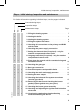
Index Index Initial start-up, inspection, maintenance Steps – initial start-up, inspection and maintenance .................................... Further details regarding the individual steps .............................................. 5 7 Coding Code 1........................................................................................................ 39 Code 2........................................................................................................
Initial start-up, inspection, maintenance Steps – initial start-up, inspection and maintenance For further information regarding individual steps, see the pages indicated. Commissioning steps Inspection steps Maintenance steps ! • • • • • • • ! • ! • 5692 619 GB • • • • • • 1. Filling the heating system . . . . . . . . . . . . . . . . . . . . . . . . . . . . . . . . . . . . . . . . . . . . . . . . . 7 2. Venting the boiler . . . . . . . . . . . . . . . . . . . . . . . . . . . . . . . . . . . . .
Initial start-up, inspection, maintenance Steps – initial start-up, inspection and . . . (cont.) Commissioning steps Inspection steps Maintenance steps ! • • ! • 20. Checking the condensate drain and cleaning the siphon . . . . . . . . . . . . . . . . . . . . . . . . . . . . . . . . . . . . . . . . . . . . . . . . . . . . . . . . . . . . . . . . . . . . . . . . . . . . . . . . . . . . . . . . 21 • • 21. Checking the neutralising system (if installed) • • 23. Cleaning the DHW cylinder . . . . . . . .
Initial start-up, inspection, maintenance Further details regarding the individual steps Filling the heating system ! Please note Unsuitable fill water increases the level of deposits and corrosion and may lead to boiler damage. & Thoroughly flush the entire heating system prior to filling with water. & Only use fill water of potable quality. & Fill water with a water hardness in excess of 3.58 mmol/l must be softened, e.g. with the small softening system for heating water (see the Vitoset pricelist).
Initial start-up, inspection, maintenance Further details regarding the individual steps (cont.) Venting the boiler 1. Close the shut-off valves on the primary side. 2. Connect the drain hose on valve A with a drain outlet. 3. Open valve A and fill valve in the heating return and vent at mains pressure, until no sound of escaping air can be heard. 4. Close valve A and fill valve in the heating return and open the primary shut-off valves. Venting the heating system 1.
Initial start-up, inspection, maintenance Further details regarding the individual steps (cont.) Filling the siphon with water 1. Remove the retaining clip and siphon A. 2. Fill the siphon with water. 3. Fit the siphon A and secure with the retaining clip. Setting the time and date (if required) – only for weathercompensated control units Note During commissioning, or after a prolonged time out of use, it may be necessary to reset the time and date, if the time flashes in the display.
Initial start-up, inspection, maintenance Further details regarding the individual steps (cont.) Pivot down the control unit for commissioning and maintenance work A Control unit B Closures C Flap D Retaining frame 1. Open flap C. 3. Release the side screws and pivot control unit A down with its retaining frame D. 5692 619 GB 2. Release side closures B and pivot control unit A forward.
Initial start-up, inspection, maintenance Further details regarding the individual steps (cont.) Checking the gas type Note In the delivered condition, the Vitodens 333 is set up for natural gas E. The boiler can be operated in the Wobbe index range 12.0 to 16.1 kWh/m 3 (43.2 to 58.0 MJ/m 3 ). 1. Determine the gas type and Wobbe index (Wo) by asking your local mains gas or LPG supplier. 2. Compare the gas category (type) and group with the details on the burner label. 4.
Initial start-up, inspection, maintenance Further details regarding the individual steps (cont.) Gas restrictor allocation Rated output Gas restrictor, internal 7 Gas & Natural gas E & Natural gas LL & LPG P kW mm mm mm 13 26 4.8 5.3 — 5.95 6.73 4.4 Function sequence and possible faults Display screen No Measures Increase set value and ensure heat is drawn off No after approx. 51 s fault F5/F9 Check fan cables and plugs No after approx.
Initial start-up, inspection, maintenance Further details regarding the individual steps (cont.) Yes Gas combination valve opens No Fault F4 Check the gas combination valve (control voltage 230 V); check the gas supply pressure No Fault F4 Check ionisation current, check electrode adjustment and gas pipe for airlocks.
Initial start-up, inspection, maintenance Further details regarding the individual steps (cont.) 4. Record the static pressure and record it in the service report on page 117. Set value: max. 57.5 mbar 5. Start up the boiler. Note During commissioning, the boiler can enter a fault state because of airlocks in the gas pipe. After approx. 5 s press "E" to reset the burner. 6. Check the supply (flow) pressure. 1. Close the gas shut-off valve. 2.
Initial start-up, inspection, maintenance Further details regarding the individual steps (cont.) 8. Shut down the boiler, close the gas shut-off valve, remove the pressure gauge and close test nipple A with the screw. 9. Open the gas shut-off valve and start the boiler. Danger Gas escaping from the test nipple leads to a risk of explosion. Check test nipple A for soundness. Setting the max. output Note The maximum output can be limited for heating operation.
Initial start-up, inspection, maintenance Further details regarding the individual steps (cont.) We recommend that your heating engineer carries out a simple leak test during the commissioning of your system. For this it would be sufficient to check the CO 2 concentration in the combustion air at the annular gap of the balanced flue pipe. The flue pipe is deemed to be sound if the CO 2 concentration in the combustion air is no higher than 0.2 % or the O 2 concentration is at least 20.6 %.
Initial start-up, inspection, maintenance Further details regarding the individual steps (cont.) Removing the burner and checking the burner gasket (replace gasket every two years) A B C D E Nuts Differential pressure sensor Burner gasket Gas supply pipe Gas train 1. Switch OFF the control unit ON/ OFF switch and the power supply. 5692 619 GB 2. Close the gas shut-off valve and safeguard against reopening. 3.
Initial start-up, inspection, maintenance Further details regarding the individual steps (cont.) 6. Check the burner gasket C for damage. Generally replace the burner gasket every 2 years. Checking the burner gauze assembly A Torx screws B Burner gauze C Burner gauze gasket D Ionisation electrode E Ignition electrodes 1. Remove electrodes D and E. 4. Insert a new burner gauze assembly with a new gasket and secure it with six Torx screws. 2.
Initial start-up, inspection, maintenance Further details regarding the individual steps (cont.) Checking and adjusting the ignition and ionisation electrodes A Ignition electrodes B Ionisation electrode C Gasket 1. Check electrodes A and B for wear and contamination. 3. Check clearances. If the gaps are not as specified or the electrodes are damaged, replace and align the electrodes together with new gaskets C. Tighten the electrode fixing screws with 2 Nm. 2.
Initial start-up, inspection, maintenance Further details regarding the individual steps (cont.) Cleaning the combustion chamber/heating surfaces and fitting the burner 2. Apply a solvent/potassium-free cleaning agent if residues remain: & Remove soot deposits with alkaline cleaning agents with additional surfactants (e.g. Fauch 600). & Remove coatings and surface discolouration (yellow-brown) with slightly acidic, chloride-free cleaning agents based on phosphoric acid (e.g. Antox 75 E).
Initial start-up, inspection, maintenance Further details regarding the individual steps (cont.) Checking the condensate drain and cleaning the siphon 1. Check that the condensate can freely drain at siphon A. 2. Remove the retaining clip and the siphon. 3. Clean the siphon. 4. Fit the siphon and secure with the retaining clip. Testing the anode earth current with an anode tester Note We recommend that the magnesium anode function is checked annually.
Initial start-up, inspection, maintenance Further details regarding the individual steps (cont.) Cleaning the DHW cylinder Note DIN 1988 requires a visual inspection and (if necessary) cleaning every two years after the cylinder has been taken into use and thereafter according to requirements. 4. Remove loose deposits with a high pressure cleaner. ! Please note Only use plastic utensils for cleaning the inside of the cylinder. 5.
Initial start-up, inspection, maintenance Further details regarding the individual steps (cont.) Returning the DHW cylinder to use A Flange lid B Gasket C Earth cable D Push-on tab 1. Reconnect the DHW cylinder to the pipework. 3. Fit the flange lid and tighten the screws with a maximum torque of 25 Nm. 2. Insert new gasket B underneath the flange lid A. 4. Push earth cable C onto push-on tab D. 5. Fill the cylinder with potable water.
Initial start-up, inspection, maintenance Further details regarding the individual steps (cont.) Flue gas emissions test The Vitodens 333 is set up in the factory for natural gas E and can, with the aid of a conversion kit, be converted to natural gas LL or LPG P (only 26 kW). During commissioning or maintenance, check the CO 2 level at the flue outlet. Note The MatriX burner of the Vitodens 333 is preset for the entire gas group. Therefore, the burner requires no further setting or adjustment.
Initial start-up, inspection, maintenance Further details regarding the individual steps (cont.) 5. Record the actual value on page 117 of the commissioning/ service report. 7. Check the CO 2 content. If the value lies outside the above range, take the measures listed on page 24. 6. Select the upper rated output. Constant temperature control unit: Press K + d simultaneously: "1" is shown. Press a: "2" is shown. Weather–compensated control unit: Press K + d simultaneously: "Relay test" is shown.
Initial start-up, inspection, maintenance Further details regarding the individual steps (cont.) Checking the ionisation current 2. Adjusting the upper output: Constant temperature control unit: Press K + d simultaneously: "1" is shown. Press a: "2" is shown. Weather–compensated control unit: Press K + d simultaneously: "Relay test" is shown in the display. Press a: "Full load" is shown in the display. A Adaptor line (accessories) 1. Connect the test instrument according to the adjacent diagram. 3.
Initial start-up, inspection, maintenance Further details regarding the individual steps (cont.) 5. Record the actual value in the service report on page 117. Matching the control unit to the heating system Note The control unit must be matched to the system equipment. Various system components are recognised automatically by the control unit and the relevant codes adjusted automatically. & For the selection of an appropriate design, see the following diagrams. & For coding steps, see page 39.
Initial start-up, inspection, maintenance Further details regarding the individual steps (cont.
Initial start-up, inspection, maintenance Further details regarding the individual steps (cont.
Initial start-up, inspection, maintenance Further details regarding the individual steps (cont.
Initial start-up, inspection, maintenance Further details regarding the individual steps (cont.
Initial start-up, inspection, maintenance Further details regarding the individual steps (cont.) Adjusting the heating curves (only for control units for weather-compensated operation) The heating curves illustrate the relationship between the outside temperature and the boiler water or the flow temperature. To put it simply: The lower the outside temperature, the higher the boiler water or flow temperature. The room temperature, again, depends on the boiler water or the flow temperature.
Initial start-up, inspection, maintenance Further details regarding the individual steps (cont.) Changing slope and level 1. Change the slope with coding address "d3" in code 1 (see page 39). Setting range 2 to 35 (equals slope 0.2 to 3.5). 2. Change the level in coding address "d4" in code 1 (see page 39). Setting range -13 to +40 K.
Initial start-up, inspection, maintenance Further details regarding the individual steps (cont.) Adjusting the set room temperature Standard room temperature Press the following keys: 1. a "1r" flashes. 2. d to select heating circuit A1 (heating circuit without mixer) or 3. a "2r" flashes. 4.
Initial start-up, inspection, maintenance Further details regarding the individual steps (cont.) Reduced room temperature Press the following keys: 1. a "1r" flashes. 2. d to select heating circuit A1 (heating circuit without mixer) or 3. a "2r" flashes. 4. d to select heating circuit M2 (heating circuit with mixer) 5. E Calling up the set night temperature.
Initial start-up, inspection, maintenance Further details regarding the individual steps (cont.) Updating the LON user list Note Only possible if all users are connected and the control unit is programmed to be fault manager (code "79:1"). Press the following keys: 1. L + d simultaneously for approx. 2 s User check initiated (see page 37). 2. e The user list is updated after approx. 2 min. The user check is completed.
Initial start-up, inspection, maintenance Further details regarding the individual steps (cont.) Implementing a user check (in conjunction with the LON system with a weather-compensated control unit) Communication with the system devices connected to the fault manager is tested with a user check. Preconditions: & The control unit must be programmed as fault manager (code "79:1"). & The LON user number must be programmed in all control units (see page 35).
Initial start-up, inspection, maintenance Further details regarding the individual steps (cont.) Scanning and resetting the "maintenance" display The red fault indicator flashes when the limits set via coding addresses "21" and "23" have been reached.
Coding Code 1 Calling up code 1 Note & On weather-compensated control units, codes are displayed as plain text. & Codes which are irrelevant (due to the system equipment level or the setting of other codes) will not be displayed. & For heating systems with one heating circuit without mixer and one heating circuit with mixer, initially the possible coding addresses "A0" to "d4" are scrolled for the heating circuit without mixer A1 and then those for the heating circuit with mixer M2.
Coding Code 1 (cont.) Coding in the delivered condition Max. boiler temp. 06:... Maximum limit of the boiler water temperature, defaulted in °C by the boiler coding card Gas type 1E:0 Operation with natural gas Venting/filling 2F:0 Program enabled Possible change 06:20 to 06:127 Maximum limit of the boiler water temperature within the ranges defaulted by the boiler 1E:1 Operation with LPG 2F:1 Ventilation program disabled Filling program enabled 2F:2 User no.
Coding Code 1 (cont.) Coding in the delivered condition Slope A1/M2 d3:14 Heating curve slope = 1.4 (only for weathercompensated control units) Level A1/M2 d4:0 Heating curve slope = 0 (only for weather-compensated control units) Possible change d3:2 to d3:35 Heating curve slope adjustable from 0.2 to 3.5 (see page 32) d4:–13 to d4:40 Heating curve level adjustable from –13 to 40 (see page 32) Code 2 Calling up code 2 Note & On weather-compensated control units, codes are displayed as plain text.
Coding Code 2 (cont.
Coding Code 2 (cont.) Coding in the delivered condition 23:0 No time interval for burner maintenance 24:0 No "Maintenance" display 25:0 i: No outside temperature sensor or fault monitoring recognised (only for constant temperature control units) No burner interval ignition Without external extension Program disabled 28:0 2E:0 2F:0 30:1 Internal variable speed circulation pump (automatic adjustment) 31:...
Coding Code 2 (cont.) Internal circulation pump 0 1 2 3 4 5 6 7 8 9 10 11 12 13 14 15 Control funct. Control funct. Control funct. Control funct. Control funct. Control funct. Control funct. Control funct. OFF OFF OFF OFF OFF OFF OFF OFF Heating circuit pump Heating circuit without mixer Control funct. Control funct. Control funct. Control funct. OFF OFF OFF OFF Control funct. Control funct. Control funct. Control funct.
Coding Code 2 (cont.) Coding Internal circulation pump 7 8 9 10 11 12 13 14 15 16 17 18 19 20 21 22 23 Control funct. OFF OFF OFF OFF OFF OFF OFF OFF ON ON ON ON ON ON ON ON Heating circuit pump Heating circuit without mixer OFF Control funct. Control funct. Control funct. Control funct. OFF OFF OFF OFF Control funct. Control funct. Control funct. Control funct.
Coding Code 2 (cont.) Coding in the delivered condition Domestic hot water 56:0 Set DHW temperature adjustable from 10 to 60 °C Possible change 56:1 Set DHW temperature adjustable from 10 to above 60 °C Note Maximum value subject to boiler coding card Observe the max. permissible DHW temperature Without auxiliary function for DHW heating 58:10 to 58:60 63:0 No default interval for auxiliary function for DHW heating (only for constant temperature control units) 63:1 65:...
Coding Code 2 (cont.
Coding Code 2 (cont.
Coding Code 2 (cont.
Coding Code 2 (cont.) Possible change 9C:0 No monitoring 9C:5 The time is adjustable to from 5 to 60 min 9C:60 9F:0 to 9F:40 Differential temperature adjustable from 0 to 40 K A0:1 With Vitotrol 200 (automatic recognition) With Vitotrol 300 (automatic recognition) A0:2 5692 619 GB Coding in the delivered condition 9C:20 Monitoring LON users. If a user fails to respond, the values defaulted inside the control unit will be used after 20 min.
Coding Code 2 (cont.) Coding in the delivered condition A3:2 Outside temperature below 1 °C: Heating circuit pump "ON" Outside temperature above 3 °C: Heating circuit pump "OFF" 5692 619 GB ! Parameters Address A3:... -9 -8 -7 -6 -5 -4 -3 -2 -1 0 1 2 to 15 Possible change A3:–9 Heating circuit pump to "ON/OFF" (see the folA3:15 lowing table) Please note When selecting a value below 1 °C there is a risk of pipes outside the thermal envelope of the house being damaged by frost.
Coding Code 2 (cont.) Coding in the delivered condition Heating circuit A1/M2 A4:0 With frost protection (only for weather-compensated control units) Possible change A4:1 No frost protection; this setting is only possible if code "A3:-9" has been selected. Note Observe the note for code "A3".
Coding Code 2 (cont.) Coding in the delivered condition Heating circuit A1/M2 A6:36 Extended economy function disabled (only for weather-compensated control units) Possible change A6:5 to A6:35 A7:0 Without mixer economy A7:1 function (only for weather-compensated control units) A8:1 Heating circuit with mixer M2 creates a demand for the internal circulation pump (only for weather-compensated control units) 5692 619 GB A8:0 Extended economy function enabled, i.e.
Coding Code 2 (cont.
Coding Code 2 (cont.) Parameter address b5:...
Coding Code 2 (cont.) Possible change E1:0 Set day temperature adjustable from 3 to 23 °C E1:2 Set day temperature adjustable from 17 to 37 °C E2:0 to E2:49 E2:51 to E2:99 E5:1 Display correction –5 K to display correction -0.1 K Display correction +0.1 K to display correction +4.9 K With external variable speed heating circuit pump (automatic recognition) E6:0 to E6:100 Maximum speed adjustable from 0 to 100 % E7:0 to E7:100 Minimum speed adjustable from 0 to 100 % of max.
Coding Code 2 (cont.
Coding Code 2 (cont.) Possible change F8:+10 Temperature limit adjusto table from F8:–60 +10 to -60 °C F8:–61 Function disabled F9:+10 to F9:–60 Temperature limit adjustable from +10 to -60 °C FA:0 to FA:50 Temperature rise adjustable from 0 to 50% Fb:0 to Fb:150 Duration adjustable from 0 to 300 min; 1 step ≙ 2 min) 5692 619 GB Coding in the delivered condition F8:–5 Temperature limit for terminating the reduced mode -5 ºC, see example on page 103. Observe the setting of coding address "A3".
Coding Code 2 (cont.) Coding in the delivered condition Heating circuit M2 F1:0 Screed drying function disabled (only for weather-compensated control units) Possible change F1:1 to F1:5 Screed drying function adjustable in accordance with five optional temperature/time profiles (see page 101) Note Observe the screed supplier's instructions. 5692 619 GB F1:6 to F1:15 Observe DIN 4725–2.
Coding Resetting codes to the delivered condition Press the following keys: 3. d to confirm or 1. L + G simultaneously for approx. 2s 4. a/b to select "Basic setting? No". "Basic settings? Yes" is displayed. 5692 619 GB 2.
Service scans Service level summary Function Temperatures, boiler coding card, brief scans Relay test 5692 619 GB Max. output (heating mode) Operating conditions and sensors Maintenance scan Key combination K and G simultaneously for approx. 2 s K and d simultaneously for approx. 2 s K and F simultaneously for approx.
Service scans Service level summary (cont.) Function Resetting codes to the delivered condition Key combination Exit L and G simultaneously – for approx. 2 s; press e Page 60 Temperatures, boiler coding card and brief scans Constant temperature control unit Press the following keys: 2. a/b for the required scan. 1. K + G simultaneously for approx. 2 s 3. d End scan.
Service scans Temperatures, boiler coding card and brief . . . (cont.) Display screen Brief scan 4 0 5 b C c 0 0 0 0 d 0 Burner control unit type Boiler type 0 Set cylinder temperature 0 Max. output in % Boiler coding card (hexadecimal) Boiler Burner control unit version version 0 0 Variable Software speed version pump variable 0 w/o speed pump 1 Wilo 0: w/o vari2 Grundfos able speed pump 5692 619 GB Weather–compensated control unit Press the following keys: 2. a/b for the required scan. 1.
Service scans Temperatures, boiler coding card and brief . . . (cont.) Display screen Set mixed flow temp. Actual mixed flow temp.
Service scans Temperatures, boiler coding card and brief . . . (cont.
Service scans Checking outputs (relay test) (cont.) Display screen 2 3 4 5 6 10 11 12 13 14 Explanation Burner modulation full load Internal pump / output 20 "ON" Heating mode diverter valve Valve, centre position DHW valve Output sK Internal extension Heating circuit pump A1 external extension Cylinder primary pump external extension DHW circulation pump external extension Central fault message external extension Weather–compensated control unit Press the following keys: 2. a/b Control relay outputs.
Service scans Scanning operating conditions and sensors Constant temperature control units Press the following keys: 1. c 2. a/b for the required operating condition. 3. d End scan.
Service scans Scanning operating conditions and sensors (cont.) Display screen Return day Outside temperature, ... °C Boiler water temperature, ... °C Flow temperature, ... °C Standard room temperature, ... °C Room temperature, ... °C Ext. set room temp, ... °C DHW temperature, ... °C Solar DHW temp., ... °C Collector temperature, ... °C Mixed flow temp., ... °C Burner, ...h Burner starts, ...
Troubleshooting Fault display Fault display structure A Fault display B Fault symbol C Fault number D Fault code The red fault indicator flashes for every fault. A fault in the burner control unit causes the display to show "E".
Troubleshooting Fault display (cont.) & & Room temperature sensor Fault - user Checking and acknowledging faults Note If an acknowledged fault is not removed, the fault message will be re-displayed after 24 h. Constant temperature control units Press the following keys: 2. d all fault messages are acknowledged simultaneously, the fault display will be cancelled and the red fault indicator continues to flash. 3.
Troubleshooting Calling up fault codes from the fault memory (fault history) The 10 most recent faults are saved and may be scanned. The faults are ordered according to date, thus the most recent fault is fault number 1. 1. G + d simultaneously for approx. 2 s 2. a/b for individual fault codes. 3. Note All saved fault codes can be deleted with e. 4. d Terminate the scan. 5692 619 GB Fault codes Fault Const. code in the display 0F X Weath.- System charcomp.
Troubleshooting Fault codes (cont.) Const. Fault code in the display 30 X Weath.- System charcomp.
Troubleshooting Fault codes (cont.) Const. Fault code in the display 92 X Weath.- System charcomp.
Troubleshooting Const. Fault code in the display b4 X Weath.- System charcomp.
Troubleshooting Fault codes (cont.) Const. Fault code in the display C2 X Weath.- System charcomp. acteristics Cause X Control mode C5 X Control mode, max. pump speed X Control mode, max.
Troubleshooting Fault codes (cont.) Const. Fault code in the display CF Weath.- System charcomp.
Troubleshooting 5692 619 GB Fault codes (cont.) Const. Fault code in the display E6 X Weath.- System charcomp.
Troubleshooting Const. Fault code in the display F8 X Weath.- System charcomp.
Troubleshooting Repairs Checking the outside temperature sensor (weather-compensated control unit) 1. Pull plug "X3" off the control unit. 2. Test the resistance of the outside temperature sensor across terminals "X3.1" and "X3.2" on the disconnected plug and compare it with the curve. 3. Where actual values strongly deviate from the curve values, disconnect the wires at the sensor and repeat test directly at the sensor. 5692 619 GB 4.
Troubleshooting Repairs (cont.
Troubleshooting Repairs (cont.) 1. & Boiler water temperature sensor Pull the leads off the boiler temperature sensor and check the resistance. & Cylinder primary temperature sensor Pull the plug % from the cable harness on the control unit and measure the resistance. & Flow temperature sensor Pull plug "X3" off the control unit and measure the resistance across terminals "X3.4" and "X3.5". 2. Check the sensor resistance and compare the actual values with the curve. 3.
Troubleshooting Repairs (cont.) Check the outlet temperature sensor 1. Pull the leads off the outlet temperature sensor A. 2. Check the sensor resistance and compare it with the curve. 3. Replace the sensor in cases of severe deviation. Danger The outlet temperature sensor is immersed in the DHW (risk of scalding). Drain the secondary side of the boiler before replacing the sensor. The flue gas temperature sensor locks out the boiler when the permissible flue gas temperature is exceeded.
Troubleshooting Repairs (cont.) 1. Pull the leads off the flue gas temperature sensor A. 2. Check the sensor resistance and compare it with the curve. 3. Replace the sensor in cases of severe deviation. Checking the plate-type heat exchanger 5692 619 GB Drain the primary and secondary side of the boiler. During removal, small amounts of water may trickle out and escape from the removed plate-type heat exchanger.
Troubleshooting Repairs (cont.) 1. Shut off and drain the boiler on the primary and the secondary side. 2. Release the side closures and pivot the control unit forward. 3. Remove the siphon. 4. Release the compression fittings A, screws B and pull out the plate-type heat exchanger C. 5. Check the primary and secondary connections for contamination and scaling; if necessary, replace the plate-type heat exchanger. A Compression fittings B Screws C Plate-type heat exchanger 6.
Troubleshooting Repairs (cont.) 1. Pull the leads off the temperature limiter. 2. Check the continuity of the temperature limiter with a multimeter. 3. Remove the faulty temperature limiter. 4. Coat the replacement temperature limiter with heat conducting paste and install. 5. After commissioning, press reset button "E" on the control unit.
Troubleshooting Repairs (cont.) Checking O-rings: A O-rings B Sensor C Plug-in connection D Adaptor 1. Pull off electrical plug C. 4. Insert the sensor with connection nipples into the gas combination valve adaptor and push in until it clicks into place. 2. Remove sensor B by pulling it upwards. 5. Reconnect the electrical plug-in connector on the sensor. 5692 619 GB 3. Ensure that both O-rings A are properly seated inside the adaptor retainers D.
Troubleshooting Repairs (cont.) Checking the fuse 3. Remove the cover. 2. Release the side closures and pivot the control unit down. 4. Check the fuse F1 (see connection and wiring diagram). 5692 619 GB 1. Switch OFF the power.
Troubleshooting Repairs (cont.) Extension kit for heating circuit with mixer Checking the rotational direction of the mixer motor Changing the rotational direction of the mixer motor (if required) 1. 1. Switch the ON/OFF switch A at the extension kit first OFF and then ON again. The device will carry out the following self-test: & Mixer "Close" (150 s) & Pump "ON" (10 s) & Mixer "Open" (10 s) & Mixer "Close" (10 s) Standard control mode then recommences.
Troubleshooting Repairs (cont.) & Switch position I for central heating return from the left (delivered condition). & Switch position II for central heating return from the right. Checking the Vitotronic 050 (accessories) 5692 619 GB The Vitotronic 050 is connected with the control unit via the LON connecting cable. To test the connection, implement a user check at the boiler control unit (see page 37).
Function description Constant temperature control unit Controls and display elements A B C D Pressure gauge Fault display (red) ON indicator (green) Reset button E Control panel: O Set boiler water temperature F Set DHW temperature O+F Emissions test function K Standby mode: L DHW only G Heating and DHW / No function b/a Setting values d Confirmation c Information e Standard setting (Reset) F ON/OFF switch The set boiler water temperature will be maintained in the "Heating and DHW" program when a deman
Function description Constant temperature control unit (cont.) Heating the DHW storage cylinder from cold The heating circuit pump is switched ON and the three-way diverter valve will be changed over, if the cylinder primary temperature sensor captures a temperature lower than the set temperature. & At a boiler water temperature ≥ set DHW temperature, the cylinder primary pump will be switched ON.
Function description Weather–compensated control unit Controls and display elements Pressure gauge Fault display (red) ON indicator (green) Reset button E Control panel: A Time program, central heating B Time program DHW heating/DHW circulation pump (if connected to the control unit) H Holiday mode D Date/time E Reduced room temperature F Set DHW temperature O+F Emissions test function K Standby mode: L DHW only G Heating and DHW M Party mode N Economy mode b/a Setting values d Confirmation c Information
Function description Weather–compensated control unit (cont.) Heating mode The control unit determines a set boiler water temperature subject to the outside temperature or room temperature (if a room temperature-dependent remote control is connected) and the slope/level of the heating curve. The determined set boiler water temperature is transferred to the burner control unit.
Function description Weather–compensated control unit (cont.) The DHW is regulated to the set temperature via the cylinder primary temperature sensor. The cylinder continues to be heated up after the draw-off process has ended, until the set DHW temperature has been reached at the cylinder primary temperature sensor. The cylinder primary pump and the three-way diverter valve remain ON for a further 30 s.
Function description Extensions for external connections Internal extension H1 An external safety valve can be connected to gD. 5692 619 GB The internal extension H1 is integrated into the control unit casing. The cylinder primary pump is connected to relay output sK.
Function description Extensions for external connections (cont.) Internal extension H2 (accessories) An external extractor fan interlock can be connected to aBJ. 5692 619 GB The internal extension H2 is integrated into the control unit casing instead of the internal extension H1. The cylinder primary pump is connected to relay output sK.
Function description Extensions for external connections (cont.) External extension H1 (accessories) aVD & External blocking (terminals 2 - 3) & External demand (terminals 1 - 2) & External heating program changeover (terminal 1 - 2) The allocation of function "External heating program changeover" is set via coding address "91". aVF External set value 0 to 10 V aVG KM BUS 5692 619 GB The external extension is connected to the boiler control unit via the KM BUS.
Function description Extensions for external connections (cont.) External extension H2 (accessories) aVD & External blocking (terminals 2 - 3) & External demand (terminals 1 - 2) & External heating program changeover (terminal 1 - 2) The allocation of function "External heating program changeover" is set via coding address "91". aVG KM BUS 5692 619 GB The external extension is connected to the boiler control unit via the KM BUS.
Function description Control functions External heating program changeover The "Ext. heating program changeover" function is connected via the external extension input "aVD".
Function description Control functions (cont.) External demand The "External demand" function is connected via the external extension input "aVD". In coding address "34" you can select the influence the signal "External demand" should have on the connected circulation pumps. In coding address "9b" you can select the minimum set boiler water temperature in case of external demand.
Function description Control functions (cont.) Screed function The screed function enables the drying of screed. For this, always observe the details specified by the screed manufacturer. You can select various temperature profiles.
Function description Control functions (cont.
Function description Control functions (cont.) Raising the reduced room temperature During operation with reduced room temperature, the reduced set room temperature can be automatically raised subject to outside temperature. The temperature is raised in accordance with the selected heating curve up to the set standard room temperature. The outside temperature limits for the start and end of the temperature raising can be adjusted via the coding addresses "F8" and "F9".
Function description Control functions (cont.) Reducing the heat-up time During the transition from operation with reduced room temperature into operation with standard room temperature, the boiler water or flow temperature will be raised in accordance with the selected heating curve. The boiler water or flow temperature can be automatically increased.
Function description Remote control DIP switch The DIP switches are located on the PCB in the top part of the housing. Remote control The remote control affects the heating circuit without mixer A1 DIP switch setting The remote control affects the heating circuit with mixer M2 5692 619 GB When connecting a separate room temperature sensor, set DIP switch "3" to "ON".
Designs A1 X...
Designs Connection and wiring diagram – internal . . . (cont.
Designs A1 108 Main PCB A2 Power supply unit 5692 619 GB Connection and wiring diagram – external connections
Designs Connection and wiring diagram – external . . . (cont.
Parts lists Parts lists 001 Heat exchanger connecting pipe with gaskets 002 Flow pipework 003 DHW connecting pipe 004 DHW connecting pipe 005 Cylinder connecting pipe 006 Return connecting pipe 007 Gas connection flange 008 Stratification storage cylinder 009 Siphon 010 Condensate hose 012 Heat exchanger 013 Cap plate (with item 014) 014 Profiled gasket 015 Clip nut 016 Mounting bracket closure 017 Boiler adaptor 018 Plug 019 Air inlet gasket Ø 125 020 Lip seal Ø 80 021 Boiler connection grommets 022 Conn
Parts lists Parts lists (cont.
Parts lists 5692 619 GB Parts lists (cont.
Parts lists 5692 619 GB Parts lists (cont.
Parts lists 5692 619 GB Parts lists (cont.
Parts lists 5692 619 GB Parts lists (cont.
Parts lists 5692 619 GB Parts lists (cont.
Commissioning/service reports Commissioning/service reports Setting and test values Set value Static pressure Date: By: mbar Supply pressure (flow pressure) = for natural gas E mbar = for natural gas LL mbar = for LPG mbar Initial start-up Maintenance/service max. 57.5 mbar 17.457.5 mbar 17.457.5 mbar 42.557.5 mbar Tick gas type Carbon dioxide content CO 2 & at the lower rated output % vol. & at the upper rated out% vol. put Oxygen content O 2 & at the lower rated output % vol.
Specification Specification Rated voltage Rated frequency Rated current Protection class Protection 230 V~ 50 Hz~ 6 A~ I IP X 4 D to EN 60529 Permissible ambient temperature & during operation 0 to +40 °C & during storage and transport Electronic temperature limiter setting: Temperature limiter setting Line fuse (mains) Power consumption & Circulation pump & Burner & Control unit 82 °C 100 °C (fixed) max. 16 A max. 115 W max. 60 W max.
Certificates Declaration of conformity Declaration of conformity for the Vitodens 333 We, Viessmann Werke GmbH & Co KG, D-35107 Allendorf, confirm as sole responsible body that the product Vitodens 333 complies with the following standards: DIN 4702–6 DIN 4753 EN 483 EN 625 EN 677 EN 50 165 EN 60 335 EN 61 000-3-2 EN 61 000-3-3 In accordance with the following Directives, this product is designated with _0085: 90/396/EEC 89/336/EEC 73/ 23/EEC 92/ 42/EEC 97/23/EC EC Declaration of conformity by an autho
Certificates Manufacturer's certificate according to the 1st BImSchV [Germany] We, Viessmann Werke GmbH & Co KG, D-35107 Allendorf, confirm that the Vitodens 333 product meets the NO x limits specified by the first BImSchV § 7 (2) [Germany]. Allendorf 12.07.05 Viessmann Werke GmbH&Co KG 5692 619 GB pp.
Keyword index Keyword index A Acknowledging a fault display . . . . . . . Adjusting the room temperature . . . . Anode replacement . . . . . . . . . . . . . . . . . . . . . . Anode testing . . . . . . . . . . . . . . . . . . . . . . . . . . . . . . 70 34 22 22 B Boiler temperature sensor . . . . . . . . . . . . Brief scans . . . . . . . . . . . . . . . . . . . . . . . . . . . . . . . . . . Burner gauze assembly . . . . . . . . . . . . . . . . Burner removal . . . . . . . . . . . . . . . . . . . . . . . .
Keyword index Keyword index (cont.) O Outlet temperature sensor . . . . . . . . . . . . 82 Outside temperature sensor . . . . . . . . . 79 P Parts list . . . . . . . . . . . . . . . . . . . . . . . . . . . . . . . . . . . . . 110 Plate-type heat exchanger . . . . . . . . . . . . 83 Product characteristics . . . . . . . . . . . . . . . . 118 Protective anode & Checking the anode . . . . . . . . . . . . . . . . . . . 21 R Raising the reduced room temperature . . . . . . . . . . . . . . . . . . . . . . . . .
5692 619 GB
Viessmann Limited Hortonwood 30, Telford Shropshire, TF1 7YP, GB Telephone: +44 1952 675000 Fax: +44 1952 675040 E-mail: info-uk@viessmann.com chlorine-free bleached paper Printed on environmentally-friendly, Viessmann Werke GmbH&Co KG D-35107 Allendorf Telefon: +49 6452 70-0 Telefax: +49 6452 70-2780 www.viessmann.de 5692 619 GB Compact gas fired condensing boiler Type WS3A 4.2 to 13 kW from serial no. 7190 613 ... 6.6 to 26 kW from serial no. 7190 614 ... Subject to technical modifications.