iPRO 5000TM Series Total Nitrogen/Total Sulfur (TN/TS) Analyzer Installation Procedure V 1.2 © March 2012 Thermo Fisher Scientific Registration No. 441506 SOLAAR House, 19 Mercers Row, Cambridge CB5 8BZ, United Kingdom. Telephone +44 (0) 1223 122 347400, Fax +44 (0) 1223 347402, http://www.thermoscientific.
iPRO 5000 Series TN/TS Analyzer Installation Procedure Contents 1 2 3 4 Introduction......................................................................................................................... 3 Preparations prior to the Installation .................................................................................. 3 Instrument Overview .......................................................................................................... 4 Start of the Installation ......................
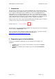
iPRO 5000 Series TN/TS Analyzer Installation Procedure 1 Introduction This manual is designed to help ensure that the iPRO 5000 Series TN/TS Analyzer will be installed efficiently. The installation must be carried out by a Thermo Fisher Scientific-trained service engineer. Detailed below is the Installation Procedure for the iPRO 5000 Series TN/TS Analyzer. It is very important that these procedures are followed in the correct order and taking account of the timing required.
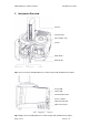
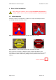
iPRO 5000 Series TN/TS Analyzer 3 Installation Procedure Instrument Overview Furnace Needle Holder Auto Sampler Tray Needle Wash Bottle Waste Bottle Perma Pure Soot Sensor Filter Fig 2.1 Front and top view iPRO 5000 Series TN/TS Analyzer with AS3000 II Autosampler Power LED Status LED Communication LED Power – On/Off Network Cable input Mains Power Input Vent Oxygen In Argon In Fig 2.2 Right side view iPRO 5000 Series TN/TS Analyzer with AS3000 II Autosampler Page 4 of 37 Version 1.
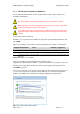
iPRO 5000 Series TN/TS Analyzer Installation Procedure 4 Start of the Installation Before starting the installation, make sure the pre-installation requirements are checked. Failure to do so can result in extended installation and possible damage. 4.1 Initial Inspection Check the contents of the shipment for completeness and possible damage in transit. See damage indicators below are correct. Fig 3.1 Example of a Tip and Tell indicator intact (left) and broken (right) Fig 3.
iPRO 5000 Series TN/TS Analyzer 4.2 Installation Procedure Packing List The packing list consists of a number of ancillary items sent with the Instrument and accessories necessary to put the system in operation. In addition a number of consumable items are included which may be used when commissioning the instrument. Check the packing list supplied with the equipment and report deviations if they occur. Note: See Appendix A below for details of parts that will be shipped with a new instrument.
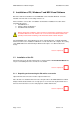
iPRO 5000 Series TN/TS Analyzer Installation Procedure 5 Installation of PC, Windows 7 and NSX Visual Software Before the NSX Visual Software for the iPRO 5000 can be installed, Windows 7 must be installed on the PC and several settings must be set. Please follow the correct order of installation and follow the Installation Procedure when performing the actions: 1. Install Windows 7 2. Change settings in Windows 7 3.
iPRO 5000 Series TN/TS Analyzer 5.1.2 Installation Procedure Finishing the installation of Windows 7 It is recommended that a Thermo Fisher Scientific trained service engineer finishes the installation of Windows 7. The responsibility of registering the Windows 7 version is with the customer. When required, involve the IT department of the customer. A possible requirement might be connecting the PC to a local network.
iPRO 5000 Series TN/TS Analyzer Installation Procedure Select the date and time setting appropriate in the next screen. Make sure the correct time zone is chosen at this point, changing it when the NSX Visual Software is running can result in loss of data. The next screen provides the opportunity the select a corporate network, when required select Work Network. When not required select Public network. Fig 4.
iPRO 5000 Series TN/TS Analyzer 5.2 Installation Procedure Configuring Windows 7 for use with the iPRO 5000 Series TN/TS Analyzer Windows 7 needs certain settings to operate without problems. Peform all actions described in this chapter, failing to do so can influence the performance of the iPRO 5000 Series TN/TS Analyzer. 5.2.1 Setup Power Options Open the Control Panel (from the Start menu in Windows). Fig 4.4 Control Panel Select Hardware and Sound. Fig 4.
iPRO 5000 Series TN/TS Analyzer Installation Procedure Select Power Options – Change when the computer sleeps. Fig 4.6 Power Options Fig 4.7 Power Options, Edit Plan Settings Set both settings to Never and Save changes. Section completed: Page 11 of 37 Version 1.
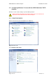
iPRO 5000 Series TN/TS Analyzer 5.2.2 Installation Procedure Setup Network Adapters Open the Control Panel. Fig 4.8 Control Panel Select View network status and tasks located in the Network and Internet category. Fig 4.9 Network and Internet Page 12 of 37 Version 1.
iPRO 5000 Series TN/TS Analyzer Installation Procedure Choose Change Adaptor settings on the left side. Fig 4.10 Change Adaptor Settings If you have 2 adapters (like in the above example) you need to assign one (choose one) to be connected to the instrument. In this case 'Local Area Connection 2' is chosen to be the connection to be connected to the instrument.
iPRO 5000 Series TN/TS Analyzer Installation Procedure Right click on the iPRO Connection adapter and choose properties. Fig 4.12 iPRO Connection Properties Un-tick all options, only select the Internet Protocol Version 4 (TCP/IPv4), press properties. Fig 4.13 Internet Protocol Properties Page 14 of 37 Version 1.
iPRO 5000 Series TN/TS Analyzer Installation Procedure Select Use the following IP address and add the IP address and Subnet mask as shown below. Fig 4.14 IP-address and Subnet Mask Press OK and Close in the next screen. Close the Network connections screen. Section completed: 5.2.3 Setup the Firewall Exclusions This procedure assumes the use of the Windows firewall.
iPRO 5000 Series TN/TS Analyzer Installation Procedure Click on Advanced settings. Fig 4.16 Windows Firewall Click on Properties in the Actions box. Fig 4.17 Advanced Settings Page 16 of 37 Version 1.
iPRO 5000 Series TN/TS Analyzer Installation Procedure Fig 4.18 Properties For Domain Profile, Private Profile and Public Profile repeat the next steps. On each of the three tabs click on the Customize...-button next to Protected network connections. Fig 4.19 Profile Tab Uncheck the iPRO Connection and press OK. Continue with the next profile, until all three are completed. Close the screen by pressing the OK button. Close all other screens and restart the PC. Section completed: Page 17 of 37 Version 1.
iPRO 5000 Series TN/TS Analyzer 5.3 Installation Procedure Installation of NSX Visual Software Do not install NSX Visual Software when the previous pages of this Installation Procedure have not been followed or the installation of Windows 7 and the setting it up for NSX Visual Software has not been as expected. Open the folder containing NSX Visual Software on the DVD disc with the iPRO 5000 Series TN/TS Analyzer. Run the file Setup.exe. This will start the installation of NSX Visual Software.
iPRO 5000 Series TN/TS Analyzer Installation Procedure Click on OK, the User Account Control will ask you for a conformation. Fig 4.22 Conformation User Account Control Click Yes, NSX Visual Software can now be installed. Run Setup.exe again. Since this PC will be connected to the iPRO 5000 Series TN/TS Analyzer, choose Local. Fig 4.23 Startup Screen NSX Visual Software Installer The installation of NSX Visual Software will now start with the extraction of the necessary files.
iPRO 5000 Series TN/TS Analyzer Installation Procedure Fig 4.24 Setup Wizard -1- Fig 4.25 Setup Wizard -2Select Everyone, click Next and follow the on-screen instructions. Fig 4.26 Setup Wizard -3When the installation is completed, click on Close. The installation of NSX Visual Software is now finished. The program (NSX Visual) will be started later during the installation procedure. Section completed: Page 20 of 37 Version 1.
iPRO 5000 Series TN/TS Analyzer Installation Procedure 6 Installation of the iPRO 5000 Series TN/TS Analyzer The installation must be carried out by a factory approved service engineer. It is very important that these procedures are followed, in correct order and taking account of the timing required. Failure to do so can result in extended installation and possible damage to teh instrument. The procedures and timings are designed to prevent problems with the NSX Visual Software, firmware and hardware.
iPRO 5000 Series TN/TS Analyzer 6.4 Installation Procedure Bottle Compartment Place the tubing for the waste in the bottle for the waste (left bottle) and the tubing for the solvent in the bottle for the solvent (right bottle). Make sure the correct bottles are used and pay attention to the size of the tubing and its corresponding hole in the cap of the bottle. Make sure the tubing of both bottles is correctly placed. For the waste bottle the tubing should end just under the surface of the cap.
iPRO 5000 Series TN/TS Analyzer 6.5 Installation Procedure AI/AS3000 II Autosampler Check which sampler tray is used and take the appropriate positioning tray. The delivery of the tray depends on the order placed. There are two possibilities; both are shown in the pictures below, the 105-position tray (top) and the 8-position tray (bottom). Fig 5.2 Positioning tray with and without the corresponding sample tray Section completed: 6.5.
iPRO 5000 Series TN/TS Analyzer 6.5.2 Installation Procedure Placing the positioning tray Use four screws to mount the correct positioning tray on top of the iPRO 5000 Series TN/TS Analyzer. Section completed: 6.5.3 Placing the AS3000 II Autosampler Place the AS3000 II Autosampler on top of the iPRO 5000 Series TN/TS Analyzer and do not bolt it down. Do not place the tray at this moment.
iPRO 5000 Series TN/TS Analyzer Installation Procedure Install M4 screws with washers on the right side of the AS3000 II Autosampler using a ballend Allen key. Do not use a straight Allen key since it may damage the thread. Tighten the screws fully. Remove the centring plate and install M4 screws with washers on the left side of the AS3000 II Autosampler. Check if all 4 screws are fully tightened. Fig 5.6 Tightening the screws Section completed: 6.5.4 Place the centring plate.
iPRO 5000 Series TN/TS Analyzer Installation Procedure Install the 105- or 8-position tray. Make sure that it is level with the sampler base casting. Fig 5.8 Placing the tray Section completed: 6.5.5 Placing the needle Open the transparent door of the AS3000 II Autosampler to reach the sampler needle.
iPRO 5000 Series TN/TS Analyzer Installation Procedure Connect the tubing from the top of the Instrument to the Autosampler sampler needle. needle Place the needle holder into the needle support of the AS3000 II Autosampler.. When the transparent door is closed make sure the tubing is not obstructing the movement of the AS3000 II Autosampler. Check if the tubing is fed through the guides and well fed on the coil on the backside of the AI/AS AS 3000 II Autosampler..
iPRO 5000 Series TN/TS Analyzer 6.6 Installation Procedure iPRO 5000 Series TN/TS Analyzer Connections Make sure that the iPRO 5000 Series TN/TS Analyzer is switched off (locate the main switch at the right hand side) before connecting the power cable to a mains wall mount. Connect the power cable, network cable, vent and the gases to the iPRO 5000 Series TN/TS Analyzer. Connect the network cable from the iPRO 5000 Series TN/TS Analyzer to the PC (to the correct network card).
iPRO 5000 Series TN/TS Analyzer Installation Procedure The accessory EGM-III gas/LPG module has its own power cable. When used, connect the EGM-III gas/LPG module separately to a mains wall socket. Do not power on the instrument at this moment. Section completed: 6.7 Set the Pressure for the Gases Set the gas regulators of the gases used to the desired 5 barg pressure (range is 3-7 barg). Do not turn on the regulators at this moment. Section completed: 6.
iPRO 5000 Series TN/TS Analyzer Installation Procedure Fig 5.13 Windows Security Alert Section completed: 6.10 Connect the NSX Visual Software to the iPRO 5000 Series TN/TS Analyzer For detailed software operations, please refer to the latest version of the NSX Visual Software Manual. After logging on, the Main Window of the NSX Visual Software will open. The status should indicate SHUT DOWN at this moment.
iPRO 5000 Series TN/TS Analyzer Installation Procedure 6.11 Selecting the correct type of carrier gas Select the correct carrier gas (connected earlier during the installation) in the NSX Visual Software. If ‘Oxygen’ is selected, make sure the blind cap is used to close off the argon connection. If oxygen is chosen, it will be taken from the secondary gas. It does not need a separate oxygen connection. For more information on the NSX Visual Software settings, see the User Guide. Fig 5.
iPRO 5000 Series TN/TS Analyzer Installation Procedure 6.14 Starting Up the iPRO 5000 Series TN/TS Analyzer Execute Start Up in the NSX Visual Software. The AI/AS3000 II Autosampler will initialize itself and the iPRO 5000 Series TN/TS Analyzer will be set on default settings. The furnace and all other heated zones will start heating to the default operating temperatures. All flows will be set and the detectors will be switched on. Section completed: 6.
iPRO 5000 Series TN/TS Analyzer Installation Procedure In the tab Calibrate click the button Gas System Test. Fig 5.17 Gas System Test Follow the instructions on the screen. When prompted for using manually blocking the injection port or using the AS3000 II Autosampler, click the Autosampler button. The NSX Visual Software will now perform a Gas System Test. Fig 5.18 Select Autosampler Page 33 of 37 Version 1.
iPRO 5000 Series TN/TS Analyzer Installation Procedure If the test fails, the NSX Visual Software and the Diagnostics Guide will provide guidance for solving the problem. Section completed: 6.16 Perform an Installation Acceptance Test Perform an Installation Acceptance Test when the iPRO 5000 Series TN/TS Analyzer is ready to use. The iPRO 5000 Series TN/TS Analyzer is ready to use when all actions above are performed and the temperatures are stable.
iPRO 5000 Series TN/TS Analyzer Installation Procedure Fig 5.20 Test Run Details After clicking Continue, the NSX Visual Software will execute a verification test for the low range (0 – 50 mg/L) using the same sample introduction method and the same settings (injection volumes, injection speeds, temperatures, etc.) that were used during the Factory Test. The test might use less replicates than the Factory Test in order to save time during installation.
iPRO 5000 Series TN/TS Analyzer Installation Procedure 7 Appendix A: Parts sent with The following parts will be shipped with a new instrument. iPRO 5000 Series – Contents of Parts Sent With iPRO 5000 Series Quick Guide User Guides and Installation Guides on Disk USB Memory stick Mains power leads for iPRO Communication s cable – iPRO to PC (RJ45) Page 36 of 37 Version 1.
iPRO 5000 Series TN/TS Analyzer Installation Procedure Gas tubing Red – argon (1/16 in. x 1/8 in.) Blue – oxygen (1/16 in. x 1/8 in.) Clear – waste (3/16 in. x 1/4 in.) In-line filters for gas inputs Blind nut for unused input Bottles for wash and waste 125 ml Driver (3 mm) and Spanners (1/2 in. and 9/16 in.) for PermaPure removal Injector tool Glassware removal tool Nozzle tool Page 37 of 37 Version 1.