Osprey® 240e/450e User Guide AVStream Driver Version 4.
© 2012 ViewCast Corporation. All rights reserved. Osprey® and SimulStream® are registered trademarks of ViewCast Corporation Microsoft®, Windows®, Windows Server ®2003, AVStream®, DirectShow®, Intel® CoreDuo®, and Windows Media® Encoder are trademarks or registered trademarks of Microsoft Corporation. Any other product names, trademarks, trade names, service marks, or service names owned or registered by any other company and mentioned herein are the property of their respective companies.
Osprey 240e/450e User Guide Contents Overview ............................................................................................................................. 1 Warranties .......................................................................................................................... 1 System requirements .......................................................................................................... 2 Minimum system requirements ...........................................
Contents Device tab ......................................................................................................................... 42 No-Video Test Pattern ................................................................................................ 43 Buffers Requested....................................................................................................... 43 Diagnostic logging .....................................................................................................
Osprey 240e/450e User Guide Audio driver .......................................................................................................................81 Selecting the audio source and input volume .................................................................. 81 Audio properties page ...................................................................................................... 83 Audio formats ...........................................................................................
Osprey 240e/450e User Guide Overview Thank you for purchasing the ViewCast Osprey 240e/450e video capture card. This user guide provides step-by-step instructions for installing and using your new video capture card. For the latest ViewCast product information and news, visit our website at www.viewcast.com. Warranties For complete warranty details, refer to the specific warranty included with each product.
Overview System requirements The following system requirements relate to your Osprey® video capture card only. The video capture or encoding applications you use will likely require a much more powerful system than that which is listed below. Please consult your software documentation for applicable system requirements.
Osprey 240e/450e User Guide Installation Steps In all cases, use the setup.exe program on the product CD or in the web package if you downloaded it. The setup program automates the Plug and Play steps needed to install the drivers and ensures they are performed correctly. It also installs the bundled applets and User’s Guide. If you have multiple Osprey capture cards in the system it configures all of the boards at the same time.
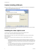
Installation Steps Custom installing AVStream During the installation process, if you choose a Custom installation, your options are limited (Figure 1). Figure 1. Osprey 240e Custom Setup screen This window allows you to choose individual components you may want to install. You can also change the location where components install. Installing the video capture card This manual covers one class of Osprey devices that include two PCI Express cards.
Osprey 240e/450e User Guide All computer cards are sensitive to electrostatic discharge. Slight electrostatic discharges from clothing or even from the normal work environment can adversely affect these cards. By following these simple guidelines, however, you can minimize the chance of damaging the Osprey video capture card. Handle cards only by the non-conducting edges. Properly ground your computer to avoid static discharge.
Installation Steps The New Hardware Wizard runs and the Found New Hardware window appears followed by the Digital Signature Not Found window (Figure 2) Figure 2. Digital Signature Not Found Window 1. 2. 3. 4. Click Continue Anyway. The Controller installing window displays, and the text inside this window changes to Osprey Video Capture Device, Installing ... Then the Digital Signature Not Found window appears on top of it. Click Continue Anyway. The Completing the Found New Hardware window displays.
Osprey 240e/450e User Guide Setting Driver Properties After installing the Osprey card and AVStream driver, you need to access the card’s settings and possibly modify them to fit your needs. This manual takes you step-by-step visually through the card settings. Start by opening the Osprey Config utility. Afterwards, we can explore the driver. You need to use a DirectShow application such as Microsoft Windows Media® Encoder or RealProducer®.
Setting Driver Properties OspreyConfig’s initial processing sequence After clicking on the Osprey Config icon, the first screen of the application appears (Figure 5) showing the cards and devices installed on your computer. Figure 5. Initial OspreyConfig user interface In this example, the computer in use has one card and four devices. The card can take a single input and stream the content differently, for example, you can use several bit rates, sizes, and formats.
Osprey 240e/450e User Guide Figure 6 shows the user interface that appears when you select a filter. We expanded the Osprey 450e Device 1A and selected Video Filter. We’ll continue with this device unless we indicate otherwise. Figure 6.
Setting Driver Properties When you choose Device 1A and Video Filter 1, the Show Properties for Selected Filter button becomes active (Figure 7). Figure 7.
Osprey 240e/450e User Guide Understanding the device properties window Osprey’s device properties window enables you to view and change the default settings of the 4.6 driver. Once you are familiar with the video card’s properties, you can make changes to get the optimum performance from your card and change settings in real time. Device properties are visible through tabs to select different controls (Figure 8). The 4.6 driver includes changes from previous versions - the tabs have changed.
Setting Driver Properties The Osprey 240e and 450e cards have the following tabs: Input Select the video input, NTSC / PAL / SECAM video standard and Input Format Video Proc Amp Set brightness, contrast, saturation, hue, gamma, and sharpness Video Decoder Select the video standard – NTSC, PAL, SECAM RefSize Set the reference size for cropping Filters SimulStream®, processing mode, gamma, deinterlace, and inverse telecine* Device Test Pattern, Capture Buffers, Diagnostic Logging Captions Set up
Osprey 240e/450e User Guide Devices and global controls The Osprey 240e and Osprey 450e video capture cards can present multiple output streams from a single input device. For example, a company may wish to do a webcast globally to resellers, users, or potential customers. Using the Filters tab, you can set up different output streams with different bit rates to accommodate users with different bandwidths. Some changes may affect the filter, such as cropping, logos, and captions.
Setting Driver Properties Input tab The source of data from an Osprey 240e/450e that streams to the Internet can come from a number of devices such as DVD players, digital cameras, camcorders, and so forth. Figure 10. Input tab The controls on the Input tab of the driver properties card have a global effect on the Osprey capture card on which they reside. If you have multiple Osprey cards, and you want to make global changes, you have to make the change on each card.
Osprey 240e/450e User Guide The Input tab has the following controls. ViewCast Video Input The Video Input section of the tab allows you to select the video signal source. Video Present This indicator is enabled when video is present. Video Standard The Video Standard allows you to select the standard different countries or geographical areas use (Figure 10) from the dropdown list. Input Format This control works with digital cameras routing through the Osprey’s card’s analog input.
Setting Driver Properties Osprey 450e AV option hardware add-on-device In addition to the standard components built into the Osprey 450e card, you can purchase the Osprey 450e AV Option hardware add-on device. The AV Option exposes additional inputs for Component and S-Video as well as balanced audio. For example, when you choose a Filter from standard Osprey 450e Device 1A; the default option provides a single video capability: Composite.
Osprey 240e/450e User Guide Video input The Video Input (Figure 16) lets you select the video signal source from a drop-down list. Figure 13. Video Input field Osprey 240e The Osprey 240e is a single channel card. It has multiple video inputs, but you can select only one of them at a time. The inputs that are selectable depend on the type of dongle used. Two types of dongles are available for this board – Composite/SVideo, and YPrPb. The connections for the Composite/SVideo dongle are shown in Figure 14.
Setting Driver Properties The Osprey -450e’s optional auxiliary expansion connector for video adds three additional inputs, over three multi-purpose physical connectors for each of the four channels: Component (YprPb) uses all three of the auxiliary video connectors S-Video (Y-C) connects an SVideo connector to two of the connectors via an adapter cable Three additional Composite inputs The labeling on the expansion panel shows which connectors to use for each purpose.
Osprey 240e/450e User Guide Input Format: analog inputs Below the Video Standard drop-down list is the Input Format (Figure 18). Figure 18. Input Format On the Osprey 240e/450e, when an analog input becomes the media source, the controls provide adjustments that improve the clarity of video from monochrome sources. When you select a composite input line and attach a monochrome device, the result is a sharper image, as shown in the notch kill item in Figure 19.
Setting Driver Properties VideoCheck VideoCheck opens a simple video monitoring window (Figure 20). You can see the immediate effect of changes to your settings. Most changes show up automatically as soon as you click Apply. You will need to click the applet’s Update button to see a change that alters the output size of the video. VideoCheck uses one preview stream of video.
Osprey 240e/450e User Guide chroma display, the small solid rectangular cursor corresponds to the luma cursor – that is, if the luma cursor is on the red color bar, the chroma cursor will be at or near the red point in the chroma display. There are also controls to set the background markings for 75 % or 100 % signal levels, and for eight or seven bars – so that the markings correspond to the type of color bars your signal generator is making.
Setting Driver Properties Video Proc Amp tab Video Proc Amp stands for Video Process Amplifier. It controls various characteristics of streaming output from Osprey 240e/450e cards. The Video Proc Amp is the second tab from the left of the Device 1A properties (Figure 23). Figure 23. Video Proc Amp Tab The Video Proc Amp uses slider controls to adjust brightness, contrast, hue, saturation, sharpness, and gamma.
Osprey 240e/450e User Guide The Video Proc Amp tab has the following controls. Brightness and Contrast These terms are used for contrast ratio. It’s a measure of a display system, defined as the ratio of the brightest color (white) to that of the darkest color (black) that the system can produce. A high contrast ratio is a desired aspect of any display, but with the various methods of measurement for a system or its part, different measured values can sometimes produce similar results.
Setting Driver Properties Video Decoder tab The Video Decoder tab is a Microsoft DirectShow standard control for setting the NTSC/PAL/SECAM video standards (Figure 24). Note: These controls are also on the Input tab. Most users find the Input tab more convenient to use. Figure 24. Video Decoder tab Changes apply to all video preview and captures pins on the currently selected device. If you have multiple Osprey cards, you can set the input individually for each of them.
Osprey 240e/450e User Guide The Video Decoder tab has the following controls. Video Standard Select the video standard Signal Detected When the card does not detect the input signal, this field displays a 0. When the card detects the input signal, it displays 1. Lines detected This field displays the number of lines the card detects in the input signal. VCR Input This field is a DirectShow feature that is not implemented. Output Enable This field is a DirectShow feature that is not implemented.
Setting Driver Properties RefSize tab Changes made to the RefSize tab (Figure 25) apply to all video previews and captures on the currently selected device. The RefSize tab controls the features related to the reference size, format, and proportions of the video. Most users can set up this page once and only refer to it occasionally since this page does not provide everyday control for the final output size of your video.
Osprey 240e/450e User Guide Source Width The Source Width control can be used to trim the black left and right edges of an image. Reference Size for Crop and Logo Placement This part of the dialog box displays the results of more fundamental settings made elsewhere in the dialog box. 525-Line (NTSC) Vertical Format This control is for NTSC users. It has no effect for PAL and SECAM 625-line video standards. OK Click OK to accept the settings.
Setting Driver Properties 16:9 Wide Use WideScreen Signal (WSS) Select 16:9 Wide for 1.85:1 anamorphic video such as DVD content and any widescreen content. The output video size is 852 x 480 for 525-line standards, and 1024 x 576 for 625-line standards. To actually see output of this size, you have to also select this size in your application. The Use WideScreen Signal (WSS) control enables automatic sidebars and letterboxing when the input video aspect ratio does not match the output aspect ratio.
Osprey 240e/450e User Guide You can set start lines all the way up to 27/290. (On the PCI products which have a Direct Mode option, PostProcessing Mode must be set in order to have top lines below 23/286.) When the start lines are below 23/286, the bottom of the video frame spills off the bottom of the 485line NTSC-standard frame. In this case, the driver adds black lines at the bottom of the frame. Note: If you select start line 21/284, Closed Captions cannot be decoded.
Setting Driver Properties The driver performs the source width adjustment in hardware if possible; otherwise it performs it in software. The following table summarizes the behavior of the control. The Adds CPU column refers to whether setting the control to a value other than 720 increases CPU usage beyond what is required by other aspects of the format.
Osprey 240e/450e User Guide 525-Line (NTSC) Vertical Format Figure 30. 525-Line (NTSC) Vertical Format This control is only meaningful for NTSC users. It has no effect for PAL and SECAM 625-line video standards. Select 480-line video for all normal applications. Select 485-line video for specialized applications. When you select 480-line video, you can select which video lines should be the top line of displayed or captured video.
Setting Driver Properties Filters tab The Filters tab (Figure 31) covers two independent technologies: SimulStream and deinterlacing. Functionality for both technologies exists on the Filters tab. Figure 31. Filters tab The RefSize tab has the following controls. 32 SimulStream Enables SimulStream to output the same video in different sizes, color formats, frame rates, crops, logos, and captioning.
Osprey 240e/450e User Guide Help Click Help to access the user guide. Filters have two interrelated purposes: They allow applications to enumerate and list DirectShow video capture and preview pins or streams (each with different settings) as named entries in their video device select list. You can set up the driver to show 1 to 10 filters per device. Each filter has one preview pin and one capture pin.
Setting Driver Properties The driver includes a free evaluation version. Evaluation mode works the same as licensed SimulStream except that an evaluation mode graphic is always displayed on the video. For details about purchasing and installing SimulStream, refer to the ViewCast website. The check box at the top of the group turns on SimulStream for the currently selected device.
Osprey 240e/450e User Guide list of capture devices with SimulStream enabled, Osprey 240 Video Device 1.1, Osprey 240 Video Device 1.2, and …1.3 and …1.4 appear. For the Osprey-450e, the corresponding designations would add an “A”. “B”, “C”, or “D” to indicate the channel number on the board. Therefore, for “Osprey-450e Video Device 1A”, when SimulStream is enabled, you will see “Osprey-450e Video Device 1A.1”, “Osprey-450e Video Device 1A.2”, and “…1A.3” and “…1A.4”.
Setting Driver Properties Deinterlace Figure 35. Deinterlace settings The deinterlace group has four radio buttons. Auto Apply inverse telecine deinterlacing to all telecine video. Apply motion adaptive deinterlacing to all video that is not telecine. Switch dynamically between the two modes as the content changes. Available for NTSC video only. Inverse Telecine Apply inverse telecine deinterlacing to all telecine video. Perform no deinterlacing of video that is not telecine.
Osprey 240e/450e User Guide Vertical scaling: When the driver scales video it treats both fields of the frame as a single progressive frame unit. The frame has to be deinterlaced or progressive. If it is not, and the video has motion, the result in scaled video will be large jagged patches on vertical or diagonal edges. If you see these effects, you need to turn on deinterlacing (see Notes).
Setting Driver Properties Currently Using group These indicators allow you to see the current algorithm. These are not control buttons; they are readonly indicators. They are mainly useful in Auto Mode, to indicate which algorithm – Inverse Telecine or Motion Adaptive – is currently being applied. They are also useful in Inverse Telecine mode to show whether telecine content is present and the Inverse Telecine algorithm is being applied. A green arrow (Figure 36) marks the mode currently in use.
Osprey 240e/450e User Guide Adaptive Deinterlace window Use the adjust dialog to adjust the parameters that control motion adaptive deinterlacing (Figure 37). Note: When the driver is using the Inverse Telecine algorithm, either in Telecine mode or Auto mode, the Adjust settings have no effect at all, and Test Mode is inoperative. Figure 37. Adaptive Deinterlace window The Adaptive Deinterlace window has the following controls.
Setting Driver Properties deinterlacing but uses slightly more processing power. The 3-frame algorithm adds one frame time of latency to video processing, whereas the 2-frame algorithm (when used in pure Motion Adaptive mode) does not (see Effects on video latency). The 2-frame algorithm is the default because of the reduced latency, and because the quality difference is hard to see. Note: The choices for deinterlacing algorithms are revised for the 4.6.1 driver.
Osprey 240e/450e User Guide Motion Adaptive – 2-frame. Once that is done, other factors to reduce processing time are the following: Set Deinterlacing to Off rather than Motion Adaptive – 2 Frame for absolute minimum processing time. Set gamma correction to the default, 100. For SECAM video, set the hue adjustment to the default, zero.
Setting Driver Properties Device tab Device controls (Figure 38) are less often used items. Unless specifically noted, changes made on this page apply to all filters and all video previews and capture pins on the currently selected device. Unless noted, different settings may be set and stored for different devices. Figure 38. Device tab The Device tab has the following controls. 42 No-Video Test Pattern This control lets you select a pattern to display when no video signal is present.
Osprey 240e/450e User Guide OK Click OK to accept the settings. Cancel Click Cancel to reject the settings and close the window. Apply Click Apply to apply the settings. Help Click Help to access the user guide. No-Video Test Pattern You can select one of four patterns to appear when no video signal is present – 75% color bars, 100% color bars, solid blue, and solid black. The 75 % color bars are calibrated to show correct luma and chroma test patterns on a vector scope.
Setting Driver Properties Capture and encoding applications generally need a large number of buffers so they can deeply pipeline the downstream processing without danger of buffer starvation at the driver. If buffer starvation is evident, in the form of dropped frames, you can try increasing the number of buffers allocated for the Capture pin. Preview video that is directly rendered on the screen does not use deep pipelining and cannot benefit from it.
Osprey 240e/450e User Guide Log to File enables writing diagnostics directly to a file. Select a directory and file name to complete the setup. For this purpose, Select File displays a standard Windows file select sub-dialog. If you do not select a file, the default will be c:\diag240-1.log. If you select a file that already exists, that file will be appended to. You can specify the maximum size that this file is allowed to grow to. The number in the dialog is this size in megabytes.
Setting Driver Properties Device Info Figure 42. Device Info The Device Info window displays useful information about the capture card and the driver, including the DirectShow name of the device (Figure 42). Click OK to close the window. Board Numbering When you first set up a system with multiple Osprey boards, the device numbers reflect the order in which the system identified and initialized the boards.
Osprey 240e/450e User Guide Figure 43. Board Numbering Each line represents the information for one Osprey board. Only boards that are currently installed and enabled are shown. Also, only boards of one type at a time are shown. For example, consider a system with two Osprey-240e and two Osprey-450e boards. The two board types are numbered separately -there is a board 1 and a board 2 of each kind. Which listing is shown depends on the context in which you open the property pages.
Setting Driver Properties issues before saving the numbers and exiting. However, you can exit by clicking Cancel at any time, and your changes will be discarded. The new numbering takes effect when you restart the system. Notes 48 Board settings, especially video custom properties such as Crop, Logo, and Captions settings, are linked to board PCI addresses rather than to board numbers. After you renumber boards, you may have to re-set your volume levels.
Osprey 240e/450e User Guide Extras Extras (Figure 45) are features of the AVStream driver that are new, not fully defined, or subject to change. Extras may also include workarounds to unresolved issues that may be resolved at a future time. Extras should be expected to change more frequently than other aspects of the driver, and may not be shown for all versions of the drivers. Figure 45. Extras Extras should be expected to change more frequently than other aspects of the driver.
Setting Driver Properties Captions tab The Osprey 240e/450e driver has four ways of delivering NTSC Closed Caption (CC) data: It can render captions directly on to the video before it leaves the driver. It can send decoded caption data to a DirectShow-compliant CC pin. It can send the raw, undecoded Line 21 caption waveform to a DirectShow-compliant VBI pin. It can deliver decoded caption data to a proprietary interface that can be used by C++ developers.
Osprey 240e/450e User Guide The Captions tab has the following controls. Pin Select The drop-down list has three choices: Capture Preview Both Render NTSC Closed Captions On Video The driver can render closed captions on video when NTSC video is selected on the input. Render Logical White as This control group maps white captions to a color other than white.
Setting Driver Properties Render NTSC Closed Captions On Video Figure 47. Render NTSC Closed Caption On Video When you select Render NTSC Closed Captions On Video (Figure 47), the CC Channel control selects which channel to render. The details of Closed Caption channels are beyond the scope of this description – refer to the EIA-608 standards document. But CC 1 is by far the most commonly used channel. Select CC 1 unless you have specific knowledge that you want to render another channel.
Osprey 240e/450e User Guide CC Pin Figure 49. CC Pin This group controls whether the closed-caption character pairs the DirectShow CC pin emits are from Field 1 or Field 2 of the video. The DirectShow specification is that CC on a CC pin is always from Field 1; however, this extension allows application developers to access Field 2 data including XDS data (such as V-chip data) via the standard DirectShow CC pin.
Setting Driver Properties Logo tab Figure 50. Logo tab The Logo tab has the following controls. Pin Select 54 The drop-down list has three choices: Capture Preview Both Enable Logo on File and Color sub tab From this control, enable or disable the logo. Enable Key Color on File and Color sub tab Control the key color and efficiency effect.
Osprey 240e/450e User Guide Weighting on File and Color sub tab Set the degree of transparency of the logo. Position and Size sub tab Set the position of the logo and the scale. OK Click OK to accept the settings. Cancel Click Cancel to reject the settings and close the window. Apply Click Apply to apply the settings. Help Click Help to access the user guide. The logo property superimposes a graphic over captured video using the logo property controls (Figure 50).
Setting Driver Properties Pin Select You can have different setups for the two pins. For example, you could enable the logo on the capture pin but not on the preview pin, and thereby save some CPU time. Figure 51. Pin Select Capture When you click Capture, the current logo settings for the capture pin are loaded, and changes you make apply only to the capture pin, not to the preview pin. Preview The Preview button works analogously.
Osprey 240e/450e User Guide Enable Key Color Figure 53. Enable Key Color You can control the key color and the transparency effect. If video is running, you see your changes interactively. You can use these controls with both BMP and PNG images. You can use key colors with PNG images that contain embedded alpha channels, but alpha keying is superior solution. If your image editor supports alpha keying, use alpha keying and leave the key color controls disabled.
Setting Driver Properties Weighting The degree of weighting of the logo is variable through 100 steps. If the setting is 100, the logo will be 100% opaque. If the setting is 0, the logo is completely transparent and invisible. If you have set a key color, the weighting or transparency value is applied only to pixels that do not match the key color; key colored pixels are always completely transparent. You can set the weighting either with the slider or by editing the number in the edit box (Figure 55).
Osprey 240e/450e User Guide The four Nudge buttons, L, R, U, and D, move the logo left, right, up, or down exactly one pixel at a time on the output video. Since the positioning rectangle may be scaled down from the full video size, the Nudge buttons allow more accurate positioning of the logo. The slide control at the bottom right of this sub-tab controls the scaling of the logo. 1X Scale returns the size to the original size of the .bmp graphic.
Setting Driver Properties Size and Crop tab This tab (Figure 57) has two functions. It sets the default output size, whether or not you enable cropping. It enables and disables cropping, and sets the cropping area. The default output size is the video size that appears in the DirectShow pin properties dialog as the default choice. It is a pathway for setting a custom or nonstandard video size in applications that do not have a custom video sizing controls built into them.
Osprey 240e/450e User Guide Pin Select This field has three choices: Capture Preview Both Reference Size Displays the full uncropped size of the incoming video. This read-only information is determined by settings made on the Input tab and the RefSize tab. Granularity This control helps you choose crop and output sizes that observe those restrictions Enable Cropping When enabled, your video is cropped to the indicated boundaries.
Setting Driver Properties The reference width and height represent the full uncropped size of the incoming video. Your crop settings are interpreted relative to this reference size. For example, if you are capturing 525-line video, with a reference size of 640 x 480, and your crop rectangle is (0, 0, 640, 480), then your video is effectively uncropped.
Osprey 240e/450e User Guide If your Pin Select setting is Capture, only the Capture granularity box is enabled; similarly for Preview. The two small read-only edit boxes to the right of the group show the horizontal and vertical granularities for the selected color format for the selected pin type.
Setting Driver Properties cropping rectangle. The Right and Bottom boxes set the bottom right. The Width and Height boxes set the size of the rectangle. Recalc button The Recalc button recalculates whichever of the six crop edit boxes you have not filled in. For example, if you set Top, Left, Width, and Height, Recalc calculates Right and Bottom. If you set Top, Left, Right, and Bottom, Recalc calculates Width and Height.
Osprey 240e/450e User Guide Default Output Size Figure 60. Default Output Size The standard DirectShow Pin Properties dialog allows you to select the height and width of captured video (Figure 60) from a drop-down list. The drop-down list has a particular range of choices that may or may not fit your needs. The drop-down list includes one default size that may or may not fit your needs. The drop-down list includes one default size that is provided by the capture driver.
Osprey 240e/450e User Guide AVStream driver reference information DirectShow technology uses terms with specific meanings, for example, filter, pin, driver, and device. Figure 61 depicts the relationship of DirectShow terms as they apply to Osprey hardware and drivers. Figure 61. DirectShow At the bottom of this diagram are one or more physical Osprey hardware devices. For each physical device the AVStream driver creates one logical Video Device and one logical Audio Device.
AVStream Driver Reference Information Both devices, filters, and pins may have associated Properties. Properties are control parameters that can be read from or written to the component. Some Property Pages are standard Windows DirectShow pages. For example, the Property Page for an individual pin is a standard DirectShow page. The Video Proc Amp and Video Decoder Pages are also DirectShow-standard. The rest are proprietary to the Osprey driver.
Osprey 240e/450e User Guide Post-Processing mode The Osprey 240e/450e driver does more than simply move video from the hardware to the system. Its Post-Processing facility includes a variety of filters, transforms, and renderers within the driver, and supports the SimulStream option. Figure 62 depicts the Osprey Post Processing. Figure 62. Post-Processing mode Figure 62 assumes that SimulStream is activated so that more than two video pins are possible.
AVStream Driver Reference Information With SimulStream enabled, there can be multiple capture pins and multiple preview pins. Each capture and preview pin pair is on a separate filter. The maximum number of each type of pin is the same as the maximum number of filters you have elected to expose in the SimulStream control group. Any pin can produce video at any size, rate, color format, and crop setting. Of course, practical limits are imposed by the bandwidth of the machine.
Osprey 240e/450e User Guide Efficient Video Rendering The following information is primarily useful to developers, but may also be helpful for those who want to fine-tune existing applications. If you are seeing poor rendering performance, in terms of either excessive CPU utilization or jerky, stuttering video, read this section. There are at least four basic ways to render video from the capture driver onto the screen.
AVStream Driver Reference Information Preview Pin to VMR7 Figure 65. Video Mixing Renderer 7 VMR7 is short for Video Mixing Renderer 7. VMR7 is a newer renderer that is generally much faster than the old Video Renderer. When the driver is running in Direct Mode, VMR7 uses an efficient DirectDraw configuration to render with almost no CPU overhead, especially when YUY2 video is used. When the driver is running in PostProcessing Mode, DirectDraw is not used but it is still the fastest renderer.
Osprey 240e/450e User Guide Preview Pin to VMR9 Figure 66. Video Mixing Renderer 9 Video Mixing Renderer 9 is the newest video rendering method and the one on which Microsoft supposedly is basing its future development. The intent is to combine the functionality of the Overlay Mixer plus Video Renderer in one module that takes advantage of the latest developments in DirectShow.
AVStream Driver Reference Information 74 ViewCast
Osprey 240e/450e User Guide Video standards and sizes Video standard refers to whether the video signal format is NTSC, PAL, or SECAM. Depending on the exact product version you have, some or all of the following standards are available: 525-line formats: NTSC-M – North America NTSC-J – Japan 625-line formats: PAL-B, D, G, H, I – many countries in Europe and elsewhere.
AVStream Driver Reference Information RGB24 – Each pixel has three bytes (24 bits) of data – one each for red, green, and blue. This is another “true color” mode with 16.7 million colors. RGB555 – Each pixel has two bytes (16 bits) of data. There are 5 bits each of red, green, and blue data; the sixteenth bit is unused. This is a “high color” mode, also known as “5:5:5.” RGB8 (Greyscale) – The Osprey AVStream driver uses the RGB8 format for greyscale video. RGB8 is a palletized format.
Osprey 240e/450e User Guide Closed captioning (CC) The Osprey AVStream driver supports NTSC closed captions in three separate ways.
AVStream Driver Reference Information On the RefSize property page, in the control group, you must select 480-line video and the radio button to start video at either Lines 23/286 or Lines 22/285. On the Captions property page, most of the controls relate to the driver’s internal direct rendering on video. The following control selects field 1 or field 2 as the field to be streamed through the CC pin. This control is per-filter; both available pins on the filter are set the same way.
Osprey 240e/450e User Guide CC streaming interface The driver supports an Osprey custom property which provides the closed caption character stream for use by custom applications. The Osprey filter named CCLineInterp.ax, supplied with the driver package, provides user-mode support for this captioning mode. The Osprey sample applet named CCChannels.exe, also supplied with the driver package, demos a CC line interpreter and XDS (Vchip) extraction and display.
AVStream Driver Reference Information This capability requires custom programming. Refer to the Osprey AVStream SDK Users’ Guide. A sample SDK applet named TCApp illustrates the interface. Figure 69. Timecode Video Marking Timecode stamping must be enabled in the driver before it can be used, and the field and line number correctly set. To access the controls, go to the Device property tab and click Extras.
Osprey 240e/450e User Guide Audio driver Setup and control for audio are much simpler than for video. Selecting the audio source and input volume You set the audio source using the Osprey mixer driver interface. Most applications, including the Windows Media Encoder applications, interface to the mixer driver directly and expose the look and feel specific to that application. However, you can also use the default Windows interface to the mixer driver.
The Audio Driver the list of audio input and output devices, including one or more Osprey cards. When you have chosen the device, click OK, and you will be returned to the Recording Control display (Figure 71). The Osprey device is not a mixer in that it does not allow for mixing the various audio sources. Therefore, when you select one audio input, any other input you previously selected becomes unselected. The Select check box at the bottom of each source sets which source is actually being used.
Osprey 240e/450e User Guide Audio properties page Many applications, including Windows Media Encoder, display the illustrated property dialog for setting audio source and volume level. This is a general-purpose DirectShow property page that our driver has to support but which is not quite intuitive in its operation (Figure 72). Figure 72. Audio properties page To select the audio source using this dialog, select the desired input in the Pin Line: selection box, then click Enable.
The Audio Driver Audio formats The Osprey hardware supports sampling of analog audio at 32, 44.1 and 48 kHz in 16-bit PCM format. Captured audio data is down-sampled and reformatted if necessary by Microsoft system audio components, allowing an application to capture audio data in 8-bit and 16-bit mono or stereo formats at any of the following data rates: 8 kHz 11.025 kHz 16 kHz 22.05 kHz 32 kHz 44.
Osprey 240e/450e User Guide In Dual Mono mode, each audio device enumerates as two separate filters, respectively for the left and right physical inputs. The filters’ names will have L and R suffixes, for example, Osprey 230 Audio Device 1L. These filters behave for the most part like normal audio filters. When you use AudioConfig, or most other applications, you connect with either the L or R filter, one at a time, not both.
The Audio Driver Audio level This control sets the hardware Input Reference level and software-based Boost factor. The settings are separate for each input of each device, and are applied to whichever input is selected in the current application or in the system mixer. The settings displayed do not automatically update when you change inputs in the application or mixer click update to refresh the settings. In Figure 72, the Audio Level control is different depending on which input is selected.
Osprey 240e/450e User Guide Appendix A: Osprey hardware specifications Osprey 240e Environmental specifications Operating temperature range 0 to 40 C Non-operating temperature range -40 to +75 C Operating humidity range Between 5 % and 80 % (non-condensing) @ 40 C Non-operating humidity range 95 % RH (non-condensing; gradient 30 % per hour Operating altitude range 0 to 3,048 meters (10,000 feet) Non-operating altitude range 0 to 15,240 meters (50,000 feet) PCI Express Bus compliant Approximat
Appendix A: Osprey Hardware Specifications Figure 75. Osprey 240e long back plate Figure 76. Osprey 240e short back plate Figure 77.
Osprey 240e/450e User Guide Osprey 450e Figure 78.
Appendix A: Osprey Hardware Specifications 90 ViewCast
Osprey 240e/450e User Guide Appendix B: Osprey 450e audio cable Figure 79 shows the male connector on the cable. Figure 79.
Osprey 240e/450e User Guide Appendix C: Troubleshooting Color bars on video screen The Osprey 240e/450e AVStream driver has a built-in color bar generator. If color bars appear in your video preview window, video is not present on the selected video input (Figure 80). You can adjust or change the color bar display, including the text overlay on the screen, using the Device Properties tab. Figure 80.
Appendix C: Troubleshooting Poor video quality at large frame sizes Large frame sizes with the deep pixel depth (24- or 32-bit), or complex format (YVU9 or YUV12 planar), impose heavy demands on the PCI bus’ data transfer capacity. Our experience is that some systems cannot handle these formats at full frame sizes. Systems vary in their data transfer limits. The characteristics of the PCI bridge are often more important than processor speed.
Osprey 240e/450e User Guide previous Video for Windows driver, but if you have multiple Osprey cards installed you do have the option of running the Video for Windows driver on some cards and the AVStream driver on others. Unfortunately the Recording Control does not work smoothly in this situation. The Video for Windows device will always try to act like it is the selected device even if it is not. You have to manually enter Recording Control’s Options Properties dialog to select your device.
Osprey 240e/450e User Guide Index 16:9 Wide, 28 2-Frame Algorithm, 39 3-Frame Algorithm, 39 525-Line (NTSC) Vertical Format, 31 A Accessing the OspreyConfig Utility, 7 ActiveMovie Window, 79 Adaptive Deinterlace window, 39 adjust dialog, 39 Audio Level control, 86 Audio properties page, 83 Auto, 36 Auto Size check box, 65 Auto Sizes, 65 B basic reference size, 70 Board Numbering, 47 Both button, 51, 56, 61 buffers, 43 C Captions tab, 50 Capture, 44 Capture button, 51, 56, 61 Capture color format, 63 Cap
Appendix C: Troubleshooting F File and Color, 56 filtergraph, 72 filters, 13 Filters tab, 32 filters, pins, and properties, 67 G Granularity controls, 62 H Horizontal Delay, 28 Horizontal Format, 27 I Initial OspreyConfig user interface, 8 Input Format, 19 Input reference level, 86 Input Reference level, 86 Input tab, 14 Input Tab without AV option, 16 Installing the video capture card, 5 Inverse Telecine, 36 inverse telecine process, 37 K key color, 57 L Logo position, 58 Logo Position, 58 logo prope
Osprey 240e/450e User Guide R Recalc button, 64 Recording Control, 81 Reference Size for Crop and Logo Placement, 30 RefSize tab, 26 Render Logical White As, 52 Render NTSC Closed Caption On Video, 52 S Selecting a device for configuration, 9 set cropping area, 60 Show [4] filters per device, 34 Show Properties for Selected Filter button, 10 SimulStream enabled, 33 SimulStream option, 33 Size and Crop tab, 60 Source Width, 29 Square Pixel setting, 27 System Settings Change Window, 6 T telecine, 37 Test M
viewcast.com © 2012 ViewCast Corporation. ViewCast®, Niagara® (and design)TM are registered trademarks of ViewCast Corporation or its subsidiaries. All other trademarks are the property of their respective owners. Product specifications and availability may change without notice.