ViewPad 10pro User Guide Model No.
Compliance Information CE Conformity for European Countries The device complies with the EMC Directive 2004/108/EC and Low Voltage Directive 2006/95/EC. R&TTE Compliance Statement 2200 This wireless module device complies with the Essential Requirements of the R&TTE Directive of the European Union (1999/5/EC).
Important Safety Instructions 1. 2. 3. 4. 5. 6. 7. 8. 9. 10. 11. 12. 13. 14. 15. 16. 17. 18. 19. 20. DO NOT place objects on top of the ViewPad, as objects may scratch the screen. DO NOT expose the ViewPad to dirty or dusty environments. DO NOT place the ViewPad on an uneven or unstable surface. DO NOT insert any foreign objects into the ViewPad. DO NOT expose the ViewPad to strong magnetic or electrical field. DO NOT expose the ViewPad to direct sunlight as it can damage the LCD Screen.
Declaration of RoHS Compliance This product has been designed and manufactured in compliance with Directive 2002/ 95/EC of the European Parliament and the Council on restriction of the use of certain hazardous substances in electrical and electronic equipment (RoHS Directive) and is deemed to comply with the maximum concentration values issued by the European Technical Adaptation Committee (TAC) as shown below: Substance Proposed Maximum Concentration Actual Concentration Lead (Pb) 0,1% < 0,1% Mercur
Copyright Information Copyright © ViewSonic® Corporation, 2011. All rights reserved. ViewSonic®, the three birds logo, On View®, ViewMatch™, and ViewMeter® are registered trademarks of ViewSonic® Corporation. Android is a trademark of Google Inc. Use of this trademark is subject to Google Permissions. This product has an Android™ platform based on Linux, which can be expanded by a varietyof JME-based application SW.
Table of Contents Chapter 1: Product Overview Package Contents Control Buttons and Connectivity Chapter 2: Setup Power and Battery Memory Card Installation SIM Card Installation and Service Activation Network Setup Chapter 3: Basic Operation Power Up, Standby and Off Appendixes A. BIOS Menu B. Indicator Table C. Troubleshooting D.
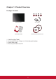
Chapter 1: Product Overview Package Contents ViewPad 10pro AC Charger User Guide and Installation Software ViewPad Series Tablet View Qu Pad ick 10 Star pro t Gu ide PC System Requirements Intel® Pentium® processor or greater running on Windows® Platform, 4x CD-ROM drive; 64MB or more of available RAM; 800x600 color display. Microsoft® Windows® 7 Professional For distribution only with a new ViewSonic® PC. This disc contains 32-bit software only.
Control Buttons and Connectivity Front Left Top Right Bottom 1. Ambient Light Sensor 12. Micro SD Card Slot 2. Webcam 13. Reset 3. Search 14. Speakers 4. Return 15. Power Indicator 5. Home Menu 16. Charger Indicator 6. Settings Menu 17. Power Button 7. Charger Jack 18. Hold and Ctrl+Alt+Del Button 8. Earphone Jack 19. Volume DOWN 9. Mini HDMI Output 20. Volume UP 10. USB Port 21. Microphone 11. SIM Card Slot 22.
Chapter 2: Setup Battery Replacement Battery is permanently fixed to the device. Battery replacement should be performed by an authorized ViewSonic service center. Please contact local ViewSonic customer service for more information. Charging Battery The new battery is only partially charged out of box. To fully charge the battery, please follow the below instruction. 1. 2. Connect one end of the AC adapter to the charger jack. Plug the other end of the AC adapter to the wall outlet to start charging.
3G SIM Card & Memory Card SIM card contains your network service details. MicroSD memory card provides additional data storage space. To install SIM/microSD card 1. MicroSD only: Open card door. 2. Insert SIM/MicroSD card as shown. Make sure the gold contacts are facing upward. 3. MicroSD only: Close the card door. Fig. 2-2 SIM & Micro SD Cards To remove the SIM card 1. Push to reject the SIM card from the slot. To remove the memory card 1. 2. 3.
Cellular Data Network (3G Data) Setup Warning: ZTE 3G does not support hot-plug detect. Please make sure the device is powered down when inserting the SIM. Inserting SIM while the device’s power is ON will cause system shutdown. 1. Power down the device. 2. Insert SIM (gold contacts facing up). 3. Power up the device. 4. At Windows desktop, tap on icon to open ZTE 3G control center. Fig. 2-3 ZTE 3G Control Center 5. After initializing, the SIM card will be detected. Fig.
Adding a New APN If data connection is unable to establish, manual configuration needs to be performed. Fig. 2-6 Carrier APN is not found Note: This device includes over 700+ worldwide APN settings. If your carrier APN is not in the list, please obtain the following information from your network service provider. - - - 1. Tap on 2. Tap on Access Point Names (APN) User Name Password icon to open setup menu. button to add a new APN. Fig. 2-7 Adding New APN 3.
Touch Panel Setup The touch panel of this device has been factory calibrated. In most cases, recalibration is not necessary. However, due to the nature of capacitive touch panel, change of geographical location may require recalibration for the new environment conditions. If touch panel is experiencing improper behavior, please perform touch panel calibration procedure as below. 1. Tap on (ILITEK) icon to open touch panel calibration menu. Fig. 2-9 Touch Panel Calibration Menu 2.
WiFi Setup 1. 2. 3. 4. In Windows task bar, left click on to bring up available access point menu. Select the WiFi access point from the available WiFi network list. Enter the password for the network if required. Click on “Connect” to complete the connection. Bluetooth Bluetooth can be configured in the Control Panel. Please refer to Control Center section for activating the Bluetooth. Pairing Bluetooth Devices 1. 2. 3. 4. 5. 6. 7. Ensure pairing devices’ Bluetooth feature is enabled.
Control Center The control center provides a quick system overall status and communication protocol (3G, WiFi and Bluetooth) setup. Main Menu Fig. 2-10 Control Center, Main Menu Tap on an icon to enter the sub-menu.
System Info Contains OS, BIOS, CPU and HD information. Battery Provide battery status and settings. Fig. 2-11 Battery, Sub-Menu Low Battery Warning Level Setting: Set the slide-bar for low battery level. Select warning notification type 1. OSD (Visual) Warning: Silent 2. Sound Warning: Audible. Save changes. Set Battery settings back to default. Gather battery usage data for battery time calculation.
Display Provide display information and adjustments. Fig. 2-12 Display, Sub-Menu Tap to manually enable external video output (If plug & play is not detected). Adjust brightness level. Power Management Power management options.
Device Controller Fig. 2-13 Device Controller, Sub-Menu Wireless Card: Tap to enable/disable WiFi. Bluetooth: Tap to enable/disable Bluetooth. No function. G-Sensor: Tap to enable/disable G-Sensor. Light Sensor: Tap to enable/disable Light Sensor. Adjust display brightness automatically based on room ambient light condition.
Chapter 3: Basic Operation Power up and off 1. Press on button located at top of device to power up. Warning: Do not turn off the device before it is fully booted or it may cause an error on the next power up. 2. In Windows 7, click Start>Shutdown> or push the button to power off. Note 1: Windows can be configured to automatically shut down by single press. Please use Windows help & support (Keyword “Power”) for more power configuration information.
Virtual Keyboard Virtual keyboard is located at upper left corner of Windows desktop. Drag the virtual keyboard to center of Windows desktop for keyboard input. Fig. 3-1 Virtual Keyboard in Desktop Virtual keyboard icon will also pop up when enter text input section. Tap on keyboard icon to bring forward the virtual keyboard. Fig.
Navigation, Front and Side Control Buttons The external buttons have different function in different OS. Button Location BIOS & DOS Windows Bluestacks (Android) Front Up Arrow Open Web Browser Open Web Browser TBD Front Down Arrow Return to Previous Return to Previous Front ESC Go to Desktop Go to Home Desktop Front Enter Open Tablet Control Panel Open Android Settings Menu Top Right Arrow Volume Up Volume Up Top Left Arrow Volume Down Volume Down Android in Windows 1. 2. 3. 4.
Chapter 4 Appendix Appendix A: BIOS Menu Main Menu - Set time and date. Provide following system configuration information. 1. BIOS Version 2. EC Version 3. PCB Version 4. Processor Type 5. Processor Speed 6. System Memory Speed 7. L2 Cache RAM 8. Total Memory Advanced Menu Quick Boot Enable quick boot. Diagnostic Splash Screen Boot-up splash screen select; graphics or text. Diagnostic Summary Screen Diagnostic summary display enable/disable. SATA Port SATA device information.
Security Menu Supervisor Password Set= Enabled; Clear= No Password. User Password Set= Enabled; Clear= No Password. Set Supervisor Password Highest level password. Set password restriction for Setup utility. Set User Password Set password restriction for Setup utility. Authenticate User on boot Enable startup password control. HDD Password State Set password restriction for HDD. Warning: Please keep track of the passwords. BIOS reset will be required for password reset.
Appendix B: Indicator Table 1. 2. Power Indicator LED ( , located on the top of device) LED Color Power Status Solid Blue ON OFF OFF Flashing Blue Sleep Battery Indicator LED ( , located on the top of device) LED Color Battery Status Solid Amber Charging Solid Blue Battery Full OFF If Power is ON; using battery power. OFF If power is OFF; OFF.
Appendix C: Troubleshooting Symptom Touch panel is not functioning properly Battery is not charging No 3G data connection Multi Touch not working Possible Causes 1. Environmental conditions are significantly different from factory default. Remedy Perform touch screen recalibration. 2. Touching surface does not provide - Ensure finger is dry and sufficient electrical charge. clean. - Ensure stylus pen is approved for capacitive touch panel use. 1.
External display not working 1. Damaged or low quality HDMI cable Change HDMI cable. 2. Output resolution and frame rate is not support by the connected display Use a display that supports the selected output resolution and frame rate. System locks up Multiple possible causes: Windows code, Intel device failure, device driver, overheating or application code. Push reset button to restart the system.
Customer Support For technical support or product service, see the table below or contact your reseller. NOTE: You will need the product serial number. Country/Region Website T = Telephone F = FAX Email Australia/New Zealand www.viewsonic.com.au AUS= 1800 880 818 NZ= 0800 008 822 service@au.viewsonic.com Canada www.viewsonic.com T (Toll-Free)= 1-866-463-4775 T (Toll)= 1-424-233-2533 F= 1-909-468-3757 service.ca@viewsonic.com Europe www.viewsoniceurope. com www.viewsoniceurope.
Limited Warranty VIEWSONIC® ViewPad What the warranty covers: ViewSonic warrants its products to be free from defects in material and workmanship, under normal use, during the warranty period. If a product proves to be defective in material or workmanship during the warranty period, ViewSonic will, at its sole option, repair or replace the product with a like product. Replacement product or parts may include remanufactured or refurbished parts or components.
Limitation of implied warranties: There are no warranties, express or implied, which extend beyond the description contained herein including the implied warranty of merchantability and fitness for a particular purpose. Exclusion of damages: ViewSonic’s liability is limited to the cost of repair or replacement of the product. ViewSonic shall not be liable for: 1.