® ViewSonic VPC190 All-in-One PC Model No.
Table of Contents Compliance Information ....................................................................................... i Important Safety Instructions ............................................................................. iii Declaration of RoHS Compliance ...................................................................... iv Copyright Information ......................................................................................... v Product Registration .............................
Moving Around and Making Selections ............................................................17 Menu ........................................................................................................18 Sub-menu .................................................................................................18 General Help ............................................................................................18 Main Menu ..........................................................................
Compliance Information For U.S.A. This device complies with part 15 of FCC Rules. Operation is subject to the following two conditions: (1) this device may not cause harmful interference, and (2) this device must accept any interference received, including interference that may cause undesired operation. This equipment has been tested and found to comply with the limits for a Class B digital device, pursuant to part 15 of the FCC Rules.
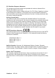
FCC Radiation Exposure Statement This equipment should be installed and operated with minimum distance 20cm between the radiator & your body. This wireless module device complies with part 15 of FCC Rules. Operation is subject to the following two conditions: (1) this device may not cause harmful interference, and (2) this device must accept any interference received, including interference that may cause undesired operation. Industry Canada Notice This wireless module device complies with Canadian RSS-210.
Important Safety Instructions 1. Read these instructions completely before using the equipment. 2. Keep these instructions in a safe place. 3. Heed all warnings. 4. Follow all instructions. 5. Do not use this equipment near water. Warning: To reduce the risk of fire or electric shock, do not expose this apparatus to rain or moisture. 6. Clean with a soft, dry cloth. If further cleaning is required, see “Cleaning the Display” in this guide for further instructions. 7.
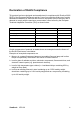
Declaration of RoHS Compliance This product has been designed and manufactured in compliance with Directive 2002/ 95/EC of the European Parliament and the Council on restriction of the use of certain hazardous substances in electrical and electronic equipment (RoHS Directive) and is deemed to comply with the maximum concentration values issued by the European Technical Adaptation Committee (TAC) as shown below: Substance Proposed Maximum Concentration Actual Concentration Lead (Pb) 0.1% < 0.
Copyright Information Copyright © ViewSonic® Corporation, 2010. All rights reserved. Microsoft®, Windows®, Windows NT®, and the Windows® logo are registered trademarks of Microsoft® Corporation in the United States and other countries. ViewSonic®, the three birds logo, OnView, ViewMatch, and ViewMeter are registered trademarks of ViewSonic® Corporation. Intel®, Pentium®, and Atom™ are registered trademarks of Intel Corporation. Award® is a registered trademark of Phoenix Technologies Ltd.
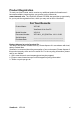
Product Registration To meet your future needs, and to receive any additional product information as it becomes available, please register your product on the Internet at: www.viewsonic.com. The ViewSonic Wizard CD-ROM also provides an opportunity for you to print the registration form, which you may mail or fax to ViewSonic. For Your Records Product Name: VPC190 ViewSonic All-in-One PC Model Number: VS13111 Document Number: VPC190-1_UG_ENG Rev.
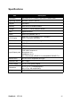
Specifications Item Description Processor Intel Atom D510, 1.66GHz, Dule Core, FSB 667 MHz Operating System Windows 7 Home Premium Chipset Intel NM10 Memory 2GB DDR2 SO-DIMM 800MHz Storage 6.35cm/2.5", SATA 5400rpm 160GB LAN Gigabit Ethernet Audio Stereo HD speakers 3W x 2 LCD Display 48cm/19" TFT LCD Display (18.5" viewable) 1366 x 768 native resolution Webcam 1.3 Mega pixel camera with digital mic. x2 Keyboard USB 100 keys Mouse USB Optical mouse Input/Output ports USB 2.
Chapter 1 Getting Started Congratulations on your purchase of the ViewSonic VPC 190 All-In-One PC! The VPC 190 All-In-One PC is engineered for powerful computing performance. Unlike conventional computers, this All-in-One PC is portable and can be easily moved anytime, anywhere. With its built-in components, it is flexible yet economical, providing users with maximum computing experience without compromising system performance.
Getting Started Package Contents Check the contents of your package. It should contain: All-in-One-PC Stand Power Cord Power Adapter Quick Guide System Recovery and User Guide Disk Driver and User Guide Disk USB Keyboard USB Mouse NOTE Your keyboard and mouse may vary depending on specific country configuration.
Getting Started Features All-in-one The functionality of a standard computer and monitor are combined together in this allin-one PC. With a built-in card reader, an optical disc drive, and I/O ports, you can connect various peripherals to maximize computer performance. Space saver The slim and sleek design provides more desk space. Because of its compactness, fewer cables are required which creates a tidy and uncluttered work space. High video quality The 48cm/19” (18.
Getting Started System Overview Front View 1 2 3 4 5 6 6 7 No. Item Description 1 Webcam Use for taking pictures, recording videos, and video conferencing. 2 Microphone Use for chatting and other interactive applications. 3 LCD display Provides visual output on a 1366 x 768 resolution display. 4 Power button Press to power on / off the All-inOne PC. 5 LCD Light Adjustment You can adjust LCD light by push "+" and "-" 6 Stereo speakers Output high quality sound with HiFi function.
Getting Started Rear View 1 2 3 4 5 No. Item Description 1 Cooling Vents Used for air convection to prevent the All-in-One from overheating. Do not cover the cooling vent. 2 VESA mount holes Mount the All-in-One PC on the wall using VESA mounts. 3 Kenstington Lock Slot Use to lock the PC. 4 RJ-45 LAN jack Connects to a local area network (LAN) using a network cable. USB port Connect USB devices such as a mouse, keyboard, printer, scanner, and other peripherals.
Getting Started SD/MMC/MS Side Views 1 61 2 3 4 5 No. Item Description 1 4 in 1 Card Reader Use to read SD (SD 2.0 included), MMC, MS, and MS Pro cards. 2 USB ports Connect USB devices such as a mouse, keyboard, printer, scanner, and other peripherals. 3 External microphone jack Connects a external microphone to the All-in-One PC. 4 Headphone jack Connects a headphone to the All-in-One PC. 5 Power jack inlet Use to connect the power adapter.
Chapter 2 Installation This chapter will guide you in installing necessary and additional components to maximize the system performance of your All-in-One PC.
Installation Attaching the Stand 1. Lay the All-in-One PC on a flat and stable surface. 2. Use a soft cloth to protect the display screen. 3. Attach the stand. Tighten the stand until it is firmly locked in place. Tighten the 3 screws on the bottom of the stand. SD/MM C/MS SD/M MC/ MS MC/M SD/M After installing the stand, the screen can be tiled up to 20° to suit user’s preference. S Tilting the Screen Removing the Stand Should there be a need to detach the stand (i.e.
Installation Connecting USB Devices Your All in One PC has six USB ports. Four are located on the side (see picture to right) and two are on the bottom of the PC. SD/MMC/MS You can connect a keyboard and a mouse using the USB ports on the rear of your All-in-One PC. Before making any connections, ensure that the All-in-One PC is turned off. Use these ports to connect USB devices, such as a printer, scanner, keyboard, mouse, USB memory drive and a digital camera among others.
Installation Connecting a USB Mouse SD/MMC/MS Plug the mouse’s cable into the USB port of the All-in-One PC. Connecting the Power 1. Connect the power adapter to the power jack of the All-in-One PC. 2. Connect the power cord to the power adapter. SD/MMC/MS 3. Plug the power cord into an electrical outlet. NOTE When disconnecting the power, always unplug the power cord from the electrical outlet first. Use the cord’s head to unplug, never pull the cable.
Installation Connecting Audio Components Connecting the Headset SD/MMC/MS Plug the stereo headphone cable into the Headphone jack (light green) of your All-in-One PC. Connecting a Microphone Plug the microphone cable into the Microphone jack (pink) of your All-in-One PC. Connecting to a Network Connect to a local area network (LAN) using the RJ45 LAN jack of your All-in-One PC. 1. Plug one end of the network cable to the RJ-45 LAN jack at the rear of your All-in-One PC. 2.
Chapter 3 Operating This chapter describes some of the basic All-in-One PC operations.
Operating Using the Power Button Turning On the All-in-One PC Press the power button to turn on your All-in-One PC. WARNING Do not turn off your computer before it fully boots or it may cause an error the next time you turn on your All-in-One PC. Turning Off the All-in-One PC In Windows 7® Home Premium, click Start > shutdown > or push the power button. NOTE You can configure Windows to automatically shut down when you press the power button.
Operating Using the Optical Disc Drive Inserting a Disc 1. Insert the disc into the drive with the disc label facing you. 2. Gently push the disc into the disc tray. Removing a Disc 1. From Windows 7, click Start > Computer. 2. Right click on the disc drive, then select Eject to eject the disc. 3. Gently pull out the disc from the disc tray. WARNING Do not remove the disc while the computer is still reading or playing it.
Chapter 4 BIOS Setup Utility BIOS Setup Utility is a program for configuring the BIOS (Basic Input/Output System) settings of the computer. BIOS is a layer of software called firmware that translates instructions from other layers of software into instructions that the computer hardware can understand. The BIOS settings are needed by your computer to identify the types of installed devices and establish special features. This chapter tells you how to use the BIOS Setup Utility.
BIOS Setup Utility When to Use the BIOS Setup Utility You need to run the BIOS Setup Utility when: • You see an error message on the screen requesting you to run Setup. • You want to restore the factory default settings. • You want to modify some specific settings of the hardware. • You want to modify some specific settings to optimize system performance. Starting BIOS Setup A keyboard is required to access and make selections in the BIOS Setup Utility.
BIOS Setup Utility Key or or Function Move cursor to top/bottom of the window Move cursor to next/previous page Go to Sub Menu <-> Select the previous value/setting of the field <+> Select the next value/setting of the field Discard Changes Load Fail Safe Defaults Load the Optimal Defaults Save Change and Exit Menu The BIOS Setup Utility is divided into Five menu categories: Main, Advanced, Boot, Security, and Exit.
BIOS Setup Utility Main Menu The Main menu lets you adjust the system time and date. It also displays the processor, memory and BIOS version information. To adjust the time, go to System Time. To adjust the date, go to System Date. Press [Tab] or [Shift Tab] to go to the next / previous field, then use + or - keys to adjust the values. Advanced Menu WARNING If you are not familiar with these settings, it is recommended to use the default configuration for the Advanced Menu options.
BIOS Setup Utility The Advanced Menu lets you view and configure the following: CPU Configuration The CPU Configuration displays your All-in-One PC’s CPU specification, such as the module version, manufacturer, frequency, speed among others. This submenu allows you to enable or disable the following settings: Max CPUID Value Limit: It is recommended that you leave it at the default setting of Disabled.
BIOS Setup Utility IDE Configuration The IDE Configuration displays the status of IDE devices installed in your All-inOne PC. When the system starts up, BIOS automatically detects the connected IDE devices. Select Primary IDE Master and press [Enter] to launch the SATA Primary IDE Master settings screen. WARNING If you are not familiar with these configurations, it is recommended to allow BIOS to auto detect the devices. Do not manually change these settings to ensure system performance.
BIOS Setup Utility USB Configuration The USB Configuration sub-menu allows you to configure the USB Configuration and USB Mass Storage Device settings. Select USB Mass Storage Device Configuration and press [Enter] to launch the USB Mass Storage Device Configuration screen.
BIOS Setup Utility Power Configuration The Power Configuration sub-menu allows you to configure the mode to restore on AC power loss. Chipset Configuration Chipset Configuration sub-menu allows you to enable or disable PXE booting.
BIOS Setup Utility Hardware Health Configuration This sub-menu displays the hardware condition of your All-in-One PC. Boot Menu The Boot menu lets you configure settings and the boot sequence to follow when the system boots up. NOTE The available sub-menu options may vary depending on the installed devices on your All-in-One PC.
BIOS Setup Utility Boot Settings Configuration With this sub-menu, you can configure the type of system boot to execute. • Quick Boot: Enable Quick Boot to allow BIOS to skip certain tests while booting. This will decrease the time needed to boot the system. • Quiet Boot: When disabled, the normal POST (Power On Self Test) messages are displayed when the system boots up. When enabled, ViewSonic logo is displayed instead. • Bootup Num-Lock: Turn the “Power-on state for Numlock” on or off.
BIOS Setup Utility Boot Menu When the ViewSonic® logo appears, quickly press the F11 button on the keyboard, Then you will enter Boot Menu. It allow you select the boot device. Security Menu The Security menu displays the security settings and lets you set up and change the supervisor or user password. Available options on this screen may vary depending on the type of passwords set. Supervisor Password The Supervisor can access and change setup utilities. He can also define the limitation of user access.
BIOS Setup Utility • View Only: Users can view the BIOS Setup Utility but cannot change the settings. User Password To set or change the user password: 1. Select Change User Password. 2. Type the password, then press [Enter]. The password can be an alphanumeric character of up to 6 characters in length. 3. Re-type the password to confirm, then press [Enter]. The Access level defined by the Supervisor determines the users’ setup utility access.
BIOS Setup Utility Exit Menu The Exit menu lets you save or discard any modifications made to the BIOS or load system default values. Save Changes and Exit Select this option to save modified settings and exit BIOS. Discard Changes and Exit Select this option to exit BIOS without saving the modified settings. Discard Changes Select this option to discard any changes. Load Optimal Defaults Select this option to load optimal default values.
Chapter 5 System Recovery Your All-in-One PC supports system recovery to enable users to restore the system to its default settings. This function is useful in the event of a system failure or when you forget system passwords.
System Recovery When to Use System Recovery You need to run system recovery: • In the event of a system or hardware failure. • You need to restore the system back to its default settings. • You forgot the system password. System recovery will format the hard disk and restore the system to its default settings. However all files and other data on drive C: will be deleted. Running ViewSonic Recovery Manager Your All-in-One PC uses ViewSonic Recovery Manager for system recovery functions.
System Recovery 3. Click Recover to Factory Default. 4. Click Yes. Another confirmation message appears, as below. 5. Click Yes. A message appears on the screen. 6. Click OK. System recovery is initiated. 7. After the system has been restored, the following window appears. 8. Click OK to restart your All-in-One PC. 9. After restarting, Windows Setup Wizard appears to help you configure basic settings. 10. Follow the on screen instructions to complete setup and start using your All-inOne PC.
System Recovery Use ViewSonic Recovery DVD Disc [Caution] ViewSonic Recovery DVD Disc will destroy all of data in hard disk. 1. Turn on the All-in-One PC. The system boots up and the ViewSonic logo appear. 2. Insert ViewSonic Recovery DVD Disc into DVD-ROM. 3. Boot from DVD-ROM 4. When the screen displays "Press any key to boot from CD or DVD...", quickly press the any key on the keyboard.. NOTE If you can not boot from DVD-ROM before you press Any Key, please restart the All-in-One PC.
Chapter 6 Troubleshooting This chapter lists some common problems that you may encounter when using your All-in-One PC and describes solutions on how to solve them.
Troubleshooting My All-in-One PC does not start. • Check that the All-in-One PC is connected to an electrical outlet and it is turned on. • Check that the power cord and all cables are connected firmly. When I turn on my computer, the message “Operating system not found” appears or Windows does not start • Check if there is a non-bootable CD inside the optical disk drive. If there is a non-bootable CD in the drive, remove the CD then restart the computer.
Troubleshooting I cannot play a DVD-ROM • If a region code warning appears when you are using the DVD player, it could be that the DVD-ROM you are trying to play is incompatible with the DVD-ROM drive in your All-in-One PC. The region code is listed on the disc’s packaging. • If you hear audio but cannot see video, your computer’s video resolution may be set too high. For best results, change the display settings, click Start >Control Panel > Settings.
Troubleshooting My microphone does not work • For webcam built-in microphone, please go to Start > Control Panel > Sounds and Audio Devices > Audio to check if it is muted. • If you are using an external microphone, check that the microphone is plugged into the Microphone connector. My mouse does not work • Check that the mouse is plugged into the mouse connector. • If you connected the mouse while your computer is on, you must restart your computer.
Chapter 7 Other Information Customer Support For technical support or product service, see the table below or contact your reseller. You will need the product serial number. Country/Region Website T = Telephone F = FAX Email Australia/New Zealand www.viewsonic.com.au AUS= 1800 880 818 NZ= 0800 008 822 service@au.viewsonic.com Canada www.viewsonic.com T (Toll-Free)= 1-866-463-4775 T (Toll)= 1-424-233-2533 F= 1-909-468-1202 service.ca@viewsonic.com Europe www.viewsoniceurope.com www.
Other information Limited Warranty VIEWSONIC® ALL-IN-ONE PC What the warranty covers: ViewSonic warrants its products to be free from defects in material and workmanship during the warranty period. If a product proves to be defective in material or workmanship during the warranty period, ViewSonic will, at its sole option, repair or replace the product with a similar product. Replacement Product or parts may include remanufactured or refurbished parts or components.
Other information Limitation of implied warranties: There are no warranties, express or implied, which extend beyond the description contained herein including the implied warranty of merchantability and fitness for a particular purpose. Exclusion of damages: ViewSonic's liability is limited to the cost of repair or replacement of the product. ViewSonic shall not be liable for: 1.