ViewSonic ™ CD4636 LCD Commercial Display - User Guide - Guide de l’utilisateur - Guía del usuario - Bedienungsanleitung - Pyководство пользователя - 使用手冊 Model No.
Compliance Information For U.S.A. This device complies with part 15 of FCC Rules. Operation is subject to the following two conditions: (1) this device may not cause harmful interference, and (2) this device must accept any interference received, including interference that may cause undesired operation. This equipment has been tested and found to comply with the limits for a Class B digital device, pursuant to part 15 of the FCC Rules.
Important Safety Instructions 1. Read these instructions completely before using the equipment. 2. Keep these instructions in a safe place. 3. Heed all warnings. 4. Follow all instructions. 5. Do not use this equipment near water. Warning: To reduce the risk of fire or electric shock, do not expose this apparatus to rain or moisture. 6. Do not block any ventilation openings. Install the equipment in accordance with the manufacturer’s instructions. 7.
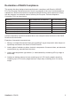
Declaration of RoHS Compliance This product has been designed and manufactured in compliance with Directive 2002/95/ EC of the European Parliament and the Council on restriction of the use of certain hazardous substances in electrical and electronic equipment (RoHS Directive) and is deemed to comply with the maximum concentration values issued by the European Technical Adaptation Committee (TAC) as shown below: Substance Proposed Maximum Concentration Actual Concentration Lead (Pb) 0,1% < 0,1% Mercury
Copyright Information Copyright © ViewSonic® Corporation, 2010. All rights reserved. ViewSonic®, the three birds logo, OnView®, ViewMatch™, and ViewMeter® are registered trademarks of ViewSonic® Corporation. Disclaimer: ViewSonic® Corporation shall not be liable for technical or editorial errors or omissions contained herein; nor for incidental or consequential damages resulting from furnishing this material, or the performance or use of this product.
CONTENTS ——————————————————————————————————————————————— Package Contents ..........................................................................................................................1 Parts Name and Functions............................................................................................................2 Control Panel .............................................................................................................................................................
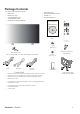
Package Contents The LCD monitor pack* should include: • LCD monitor • Power cord (1.8 m) • • • • • • • VGA Signal Cable (1.8 m) CD User Manual & QSG Remote Control and AAA Batteries Main switch cover Screw for Main Switch cover x2 Clamper x 2 Screw for Clamper x 2 Xxxxxxxxxxxxx x xxxxxxxxxxxxx xxxxxxxxxxxxx xxxxxxx CD User Manual & QSG Screw (M3 x 5) x 2 Main switch cover * The supplied power cord varies depending on destination.
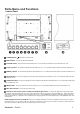
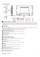
Parts Name and Functions Control Panel POWER button ( ) : To switch the power on/off. MUTE button : To switch the audio mute ON/OFF. SOURCE button : To set the function while OSD menu is on or to activate input selection menu while OSD menu is off. off. off.
Terminal Panel EXTERNAL CONTROL (mini D-Sub 9 pin) This is for serial connection when multiple monitors are connected. To achieve remote management through RS232C commands (refer to the RS232C remote control user manual), connect the RS232C OUT connector from a computer or from a different monitor to the RS232C IN connector from your monitor. The same RS232C commands can be looped through by connecting the RS232C OUT of this monitor to the next RS232C IN.
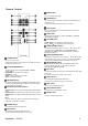
Remote Control MENU button To turn the OSD menu on/off. DOWN button To move the highlight bar down to adjust the selected item when OSD menu is on. To move the sub-picture down when in “PIP” mode. INFO. button To turn on/off the setting information displayed on the right-up corner of the screen. SIZE button To select the picture size from [FULL], [NORMAL], [CUSTOM] , [DYNAM IC] and [REAL]. VOLUME button VOL+ button: To increase the audio output level.
Operating Range for the Remote Control Point the top of the remote control towards the LCD monitor's remote sensor during button operation. Use the remote control within a distance ≤ 2 m/ 6.6 ft from the front of the LCD monitor's remote control sensor and within a horizontal and vertical angle 30° with a distance ≤ 2 m/ 6.6 ft. Handling the remote control * * * * Do not subject to strong shock. Do not allow water or other liquid to splash the remote control.
Setup Procedure 1. Install the system on the right location CAUTION: THE LCD MONITOR MUST BE MOVED OR INSTALLED BY TWO OR MORE PERSONS. Failure to follow this caution may result in injury and damage when the LCD monitor falls. CAUTION: DO NOT ATTEMPT TO INSTALL THE LCD MONITOR BY YOURSELF. The LCD display must be installed by a qualified technician. Contact your dealer for more information. CAUTION: DO NOT MOUNT OR OPERATE THE DISPLAY UPSIDE DOWN, FACE UP OR FACE DOWN.
9. Adjust the image Make adjustments to brightness or contrast if required. 10. Recommended Adjustment To reduce the risk of “image persistence”, please adjust the following items based on the application being used. “POWER SAVE”, “SCREEN SAVER“, “DATE AND TIME”. 11. To prevent the main power switch from being changed To prevent the possibility of main power switch being carelessly pushed, please attach the main switch cover (accessory) onto it.
Video wall design Guide ViewSonic CD4636 8
How to Mount and Attach Stand to the LCD Monitor You can install the LCD monitor in one of the following two ways: Method 1: Attach and remove the optional stands How to install stands 1. Please turn the monitor off. 2. After inserting stand in guide block, fasten the thumbscrews on both sides of the monitor. NOTE: Install the table stand with the longer end of the stand directing to the front. Stand is optional accessory (STND-014) In the upright position How to remove the stands 1.
To avoid monitor from falling Take measures to prevent the monitor from falling over in case of an earthquake or other disaster might occur to lessen the probability of injury and damage. As shown in the figure below, secure the monitor to a solid wall or pillar using rope (commercially available) strong enough to bear the weight of the monitor( approx. 47.5 kg). Screw hooks (commercially available), of ring type rather than C-shaped screw hooks (with opening), are recommended.
Ventilation Requirements for enclosure locating To allow heat to disperse, leave space between surrounding objects as shown in the diagram below.
Connectivity Before making connections: * * First turn off the power of all the attached equipments before make connections. Refer to the user manual included in each separate piece of equipment.
Connecting to a Personal Computer As you finish the connection between the computer and the LCD monitor, you could play the contents in the computer and display them on the LCD monitor. Connecting the LCD Monitor to a Personal Computer • To achieve this, apply the supplied VGA signal cable (mini D-sub 15 pin to mini D-sub 15 pin) to make connection between a PC and the LCD monitor (VGA IN connector).
Connecting to a Digital Interface Equipment Connections can be made between the LCD monitor and other digital equipment that is equipped with a digital interface compliant with the DVI (Digital Visual Interface) standard. Connect the LCD Monitor to a Computer with a Digital Output • The HDMI , DVI-D IN connector accepts a HDMI cable. • HDMI and DVI-D can receive HDMI video signals from either a HDMI output of for instance a DVD player or from a DVI-D output of a PC.
Connecting to a DVD Player As you finish the connection between the DVD player and the LCD monitor, you could display the contents from the played DVD on the LCD monitor. You might like to refer to your DVD player’s manual for further information. Connect the LCD Monitor to a DVD Player • To achieve this, apply a 3x components cable (Y, Pb, Pr) with BNC connectors at one end and RCA connectors at the other end between DVD player and display.
Connecting to a Stereo Amplifier You can connect your stereo amplifier to your LCD monitor. Refer to your amplifier's manual for further information. Connect the LCD Monitor to a Stereo Amplifier • Turn on the LCD monitor and the amplifier only after all connections have been finished. • Apply 2 RCA cables (audio left and right) to make connection between the amplifier (audio in) and the LCD monitor (audio out). • Do not reverse the audio left and right jacks.
Basic Operation Power ON and OFF Modes The LCD monitor power indicator will turn green while powered on and will turn red while powered off. The monitor can be powered on or off using the following three options: 1. Pressing the Main Power Switch. NOTE: When the Main Power Switch is used to power off the LCD monitor, the remote control, the power button and the indicator will not work. Make sure to turn the Main Power Switch on before using the other two options. 2. Pressing the power button.
Power Indicator Status Green Red LED Off Red Blinking * See troubleshooting Power ON Power Standby Power OFF Diagnosis (Detecting failure) Using Power Management Please turn off the LCD monitor when it will not be used for long time. This could potentially increase the life and decrease the power consumption of the LCD monitor. Standby mode: Push the power button on the remote control or on the monitor to enter the standby mode. Power Off: Push the Main Power Switch to enter the power off mode.
Smart Picture Mode HDMI, VGA STANDARD CINEMA VIVID SOFT COMPONENT, VIDEO Audio Source Switching You can select the audio source using the AUDIO SOURCE button on the remote control. HDMI HDMI AUDIO1 AUDIO2 AUDIO3 Control Lock Mode This function disables the operation o buttons so that the adjustments you make are not active when they are pressed. To disable the buttons, press and hold down the S and T buttons together for at least 3 seconds.
OSD (On-Screen-Display) Controls Remote Control Control Panel Press MENU button to open Main menu. Press UP or DOWN button to select submenu. Press EXIT button to open Main menu. Press UP or DOWN button to select. UP or DOWN button Press ENTER button to enable setting. Press UP or DOWN, and LEFT or RIGHT button to select function, or adjust the setting. Press ENTER button to enable the setting. Press SOURCE button Press UP or DOWN, and + or to enable the setting.
Main-Menu PICTURE BRIGHTNESS Adjusts the overall image and background screen brightness. Press ▶ button to increase brightness. Press ◀ button to decrease brightness. CONTRAST Adjusts the image brightness for the input signal. Press ▶ button to increase contrast. Press ◀ button to decrease contrast. SHARPNESS This function is digitally capable to keep crisp images at any timing. It is adjustable to get a distinct image or a soft one as you prefer and set independently for each picture mode.
COLOR * : INPUT HDMI , DVI-D(INPUT MODE-HD), COMPONENT, S-VIDEO, VIDEO only Adjusts the color of the screen. Press ▶ button to increase color depth. Press ◀ button to decrease color depth. COLOR TEMPERATURE Is used to adjust the color temperature. The image becomes reddish as the color temperature decreases, and becomes bluish as the color temperature increases. COLOR CONTROL The color levels of red, green, and blue are adjusted by the color bars.
Main-Menu SCREEN H POSITION Controls Horizontal Image position within the display area of the LCD. Press ▶ button to move screen to right. Press ◀ button to move screen to left. V POSITION Controls Vertical Image position within the display area of the LCD. Press ▶ button to move screen to UP. Press ◀ button to move screen to DOWN. CLOCK * : INPUT VGA only Press ▶ button to expand the width of the image on the screen the right. Press ◀ button to narrow the width of the image on the screen the left.
CUSTOM ZOOM “CUSTOM ZOOM” will be selected when you select “CUSTOM” on the screen “ZOOM” mode. ZOOM: expands the horizontal and the vertical size simultaneously. HZOOM: expands the horizontal size only. VZOOM: expands the vertical size only. H POSITION: moves to the right with + button. moves to the left with – button. V POSITION: moves up with + button. moves down with – button. SCREEN RESET Selecting Screen reset allows you to reset all OSD settings from PICTURE setting.
Main-Menu AUDIO BALANCE Adjusts the balance of L/R volume. Press ▶ button to move the stereo sound image to right. Sound of the left side will be small. Press ◀ button to move the stereo sound image to left. TREBLE This feature helps you to accentuate or reduce the high frequency sound. Press ▶ button to increase TREBLE sound. Press ◀ button to decrease TREBLE sound. BASS This feature helps you to accentuate or reduce the low frequency sound. Press ▶ button to increase BASS sound.
Main-Menu PIP (PICTURE IN PICTURE) PIP SIZE Selecting the size of picture inserted at the “Picture-in-Picture” (PIP) mode. “Large”, “Middle” and “Small” are available. PIP AUDIO Selecting the sound source in PIP mode. When selecting “MAIN AUDIO”, you will get the sound for the main picture and when selecting “PIP AUDIO”, you will get the sound for the picture instead. PIP RESET Selecting PIP Reset allows you to reset all OSD settings from PIP setting.
Main-Menu CONFIGURATION 1 AUTO ADJUST * : INPUT VGA only Press "ENTER" button to automatically adjust screen size, horizontal position, vertical position, clock, clock phase, white level and black level. Press " EXIT " button to cancel execution AUTO ADJUST and then will return to the previous menu. POWER SAVE Selecting RGB "ON", the monitor will go to power management mode when HDMI, DVI-D,VGA, sync is lost.
FACTORY RESET Selecting "YES" allows you to reset PICTURE, SCREEN, AUDIO, CONFIGURATION1,2 and ADVANCED OPTION will be back to factory settings (except LANGUAGE, DATE AND TIME and SCHEDULE). Select "YES" and press "ENTER" button to restore the factory preset data. Press " EXIT " button to cancel and return the previous menu.
Main-Menu CONFIGURATION 2 OSD TURN OFF The OSD control menu will stay on as long as it is used. In the OSD Turn Off submenu, you can select how long the monitor waits after the last touch of a button to shut off the OSD control menu. The preset choices are 5 -120 seconds. INFORMATION OSD Selects the information OSD to be displayed or not. The information OSD will be displayed when the input signal is changed or a source change or warning message like no-signal or out-of range.
Main-Menu ADVANCED OPTION INPUT RESOLUTION * : INPUT VGA only This feature makes the display controlling the source in order to match display capabilities by choice or automatically. You can select one of the following timings: (1)1024x768, 1280x768, 1360x768 and 1366x768. (2) 640x480, 720x480 and 852x480 (3) 800x600, 1064x600 and 720x576 (4) 1400x1050 and 1864x1050 (5) 720x400 and 640x400 AUTO: Determines the resolution automatically.
FILM MODE * : INPUT HDMI, DVI-D(MODE-HD), S-VIDEO, VIDEO only Selects Film mode function. AUTO: Enable the Film mode function. This mode is better suited for movies, which is converted 24 Frames/sec source to DVD Video. We recommend to select “PROGRESSIVE” in “SCAN CONVERSION”. OFF: Disable the Film mode function. This mode is better suited for Broadcasting or VCR source. IR CONTROL Selects the operation mode of the remote controller when multiple monitors are connected via RS232C.
SCHEDULE Programs the monitor's working schedule. Schedules the power on and power off by using hour and a day of the week. Also sets the input port. This OSD can't be removed except EXIT. MONITOR ID ID numbers for remote control are assigned to monitors that are multi-connected via RS232C. ID numbers 1 to 26 are selectable. DDC/CI Use to turn ON or OFF the DDC/CI communication function. Select ON for normal use.
NOTE NOTE 1: IMAGE PERSISTENCE Please be aware that LCD Technology may experience a phenomena known as Image Persistence. Image Persistence occurs when residual or “ghost” image of a previous image remains visible on the screen. Unlike CRT monitors, LCD monitors’ image persistence is not permanent, but constant images being displayed for a long period of time should be avoided. To alleviate image persistence, turn off the monitor for as long as the previous image was displayed.
NOTE 3: “PIP”, “POP” and “SIDE BY SIDE” The following table shows the combination of signal inputs under which the “PIP” and “POP” modes function. These modes do not function, however, when the screen size is “CUSTOM” or “REAL”.
Features Slim bezel A slim bezel design adds a stylish look to a public display to nicely blend in most environments. Furthermore this design is ideal for tiled matrix video walls. Zoom function for tiled matrix The internal zoom function enables easy implementation of a video wall matrix, without the need for expensive external equipment. Capable of a vidiwall of 25 displays by dividing up to 5 displays each horizontally and vertically.
Troubleshooting No picture • • • • • • The signal cable should be completely connected to the graphics card/computer. Front Power Switch and computer power switch should be in the ON position. Check to make sure that a supported mode has been selected on the graphics card or system being used. (Please consult graphics card or system manual to change graphics mode.) Check the monitor and your graphics card with respect to compatibility and recommended settings.
No Sound • • • Check to see if speaker cable is properly connected. Check to see if mute is activated. Check to see if volume is set at minimum. Remote Control does not work • • • Check the Remote Control’s batteries status. Check if batteries are inserted correctly. Check if the Remote Control is pointing at the monitor’s remote sensor. “SCHEDULE” / “OFF TIMER” function is not working properly • • The “SCHEDULE” function will be ignored when the “OFF TIMER” is set.
Specifications Specifications product Specifications Analog Input LCD Module Diagonal: Pixel Pitch: Resolution: Color: Brightness: Contrast Ratio: Response time: View Angle: Frequency Horizontal: Vertical: Pixel Clock Viewable Size Input Signal PC-Input: Digital Input 46" / 116.8 cm 0.7455 mm 1366 x 768 dots 16.7 million colors (depending on video card used) 450 cd/m2 (typ.) 4500:1 (typ.) , 3,000:1(min), 16000:1(Dynamic CR) 8 ms (typ. G to G) Up and Down 178°, Left and Right 178° (typ.) @CR>10 31.
Customer Support For technical support or product service, see the table below or contact your reseller. NOTE: You will need the product serial number. T = Telephone F = FAX Email Australia/New Zealand www.viewsonic.com.au AUS= 1800 880 818 NZ= 0800 008 822 service@au.viewsonic.com Canada www.viewsonic.com T (Toll-Free)= 1-866-463-4775 T (Toll)= 1-424-233-2533 F= 1-909-468-3757 service.ca@viewsonic.com Europe www.viewsoniceurope.com www.viewsoniceurope.com/uk/Support/Calldesk.
Limited Warranty VIEWSONIC® LCD Commercial Display What the warranty covers: ViewSonic warrants its products to be free from defects in material and workmanship, under normal use, during the warranty period. If a product proves to be defective in material or workmanship during the warranty period, ViewSonic will, at its sole option, repair or replace the product with a like product. Replacement product or parts may include remanufactured or refurbished parts or components.
Exclusion of damages: ViewSonic’s liability is limited to the cost of repair or replacement of the product. ViewSonic shall not be liable for: 1. Damage to other property caused by any defects in the product, damages based upon inconvenience, loss of use of the product, loss of time, loss of profits, loss of business opportunity, loss of goodwill, interference with business relationships, or other commercial loss, even if advised of the possibility of such damages. 2.
Mexico Limited Warranty VIEWSONIC® LCD Commercial Display What the warranty covers: ViewSonic warrants its products to be free from defects in material and workmanship, under normal use, during the warranty period. If a product proves to be defective in material or workmanship during the warranty period, ViewSonic will, at its sole option, repair or replace the product with a like product. Replacement product or parts may include remanufactured or refurbished parts or components.
Contact Information for Sales & Authorized Service (Centro Autorizado de Servicio) within Mexico: Name, address, of manufacturer and importers: México, Av. de la Palma #8 Piso 2 Despacho 203, Corporativo Interpalmas, Col. San Fernando Huixquilucan, Estado de México Tel: (55) 3605-1099 http://www.viewsonic.com/la/soporte/index.htm NÚMERO GRATIS DE ASISTENCIA TÉCNICA PARA TODO MÉXICO: 001.866.823.2004 Villahermosa: Hermosillo: Distribuciones y Servicios Computacionales SA de CV.